Tracer Lamp
2021-2022
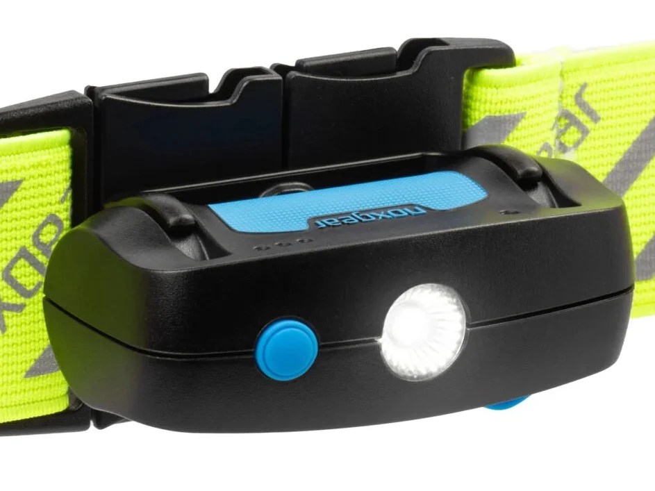
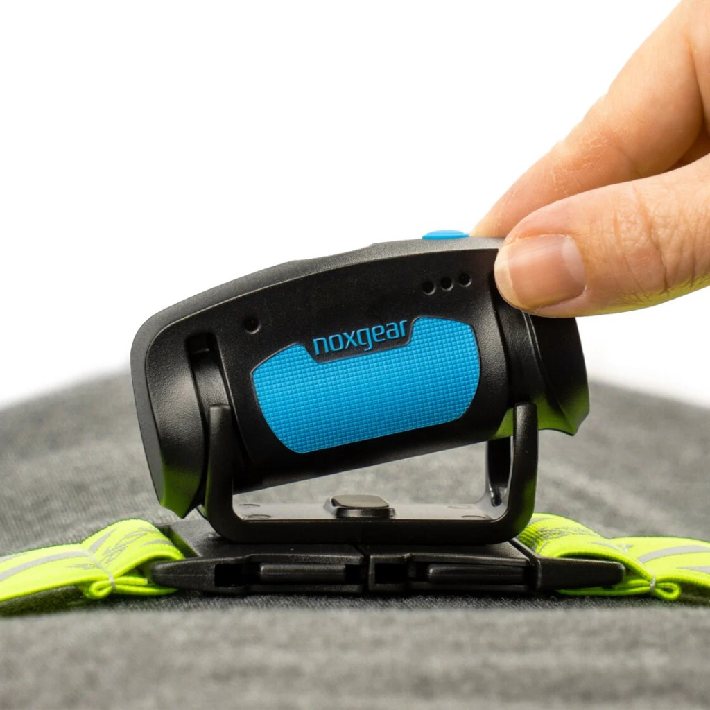
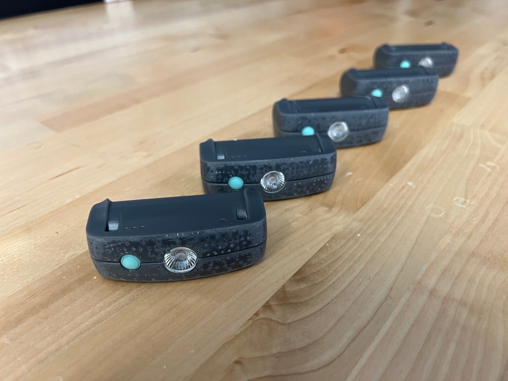
The Trace Lamp is a wearable chest lamp by Noxgear. It is the brightest and most comfortable chest lamp in the market. It is designed to integrate seamlessly into the Tracer visibility vest by Noxgear allowing you to see in the dark while also being seen by others.

Unlike other Noxgear products that existed when I joined Noxgear, the Tracer Lamp was conceived, designed and manufactured during my time. I owned the electrical design entirely and worked closely with the rest of the team on the hardware design, reliability and user experience. I will share some insights into the design and learnings from the process of bringing a product to market.

Design
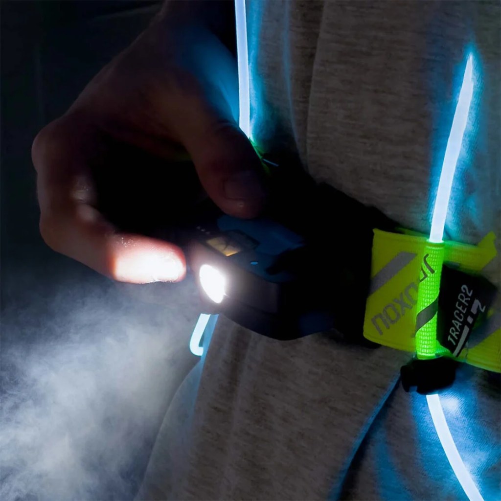
The goal when we started was to build a wearable lighting device that can illuminate your path as you walk or run. We and more importantly our customers didnt like wearing head lamps. So a chest lamp seemed like the best option. We delibrated over what would make the best chest lamp and came up with the following design goals.
- Bright enough to allow for excellent long range visibility
- Light weight so that it doesn’t bounce on your chest like crazy
- Easy and intuitive to use (if you need a manual, we have failed)
- Water resistant since its meant to be used outdoors
- Low cost so that customers can easily buy it
- Rechargeable because any other option doesn’t really work
With these goals, we set on to design a lamp. The process was long and filled with hurdles, but we learned a lot. In the end, were able to achieve our goals and ship thousands of units to customers who gave it an average rating of 4.9 stars.
Lets talk about some interesting things I learned in the process.
Lumen Lies
Yes, companies lie about lumens. While doing market and design research for the lamp, I learned that majority of the flash lights out there have light output claims (measured in lumens) that are simply not true.
If you go on Amazon and search for flash lights, you will find millions of brand-less products claiming thousands of lumens. Those are clearly false, but even reputable brands would have numbers that would sound believable but when I bought them and tested them, I learned that most of them never got to the number they advertised.

As I dug deep, I learned a couple of interesting things. One was that a lot of brands advertise the theoretical maximum light output of the emitter (fancy name for LED) that they are using. They probably weren’t driving the emitter to its maximum output anyways but even if they were, they would be loosing some percentage of light in the optics. So the actual output would be considerably lower than advertised.
The second was the ANSI FL1 standard which is what almost all reputable brands use to advertise their flashlight ratings. If you read the fine print of the standard, it says two key things.
- The lumen output advertised is the instantanous output 30 seconds after the light is turned on.
- The battery life for the specified lumen output is measured till the time the light output drops below 10% of the output measured at 30s.
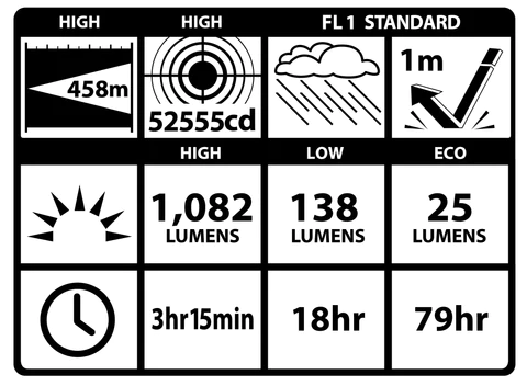
You might start to think how that could be a problem. So for a flashlight with the above rated FL1 specs, it could have 1082 lumens at 30 seconds and drop to 250 lumens at the 60 second mark. And then stay at 250 until it dies at the 3hr15min mark. That would be in agreement with the spec but as a user, you probably paid for it thinking you would get almost 1000 lumens for 3 hours whereas the reality could be so far away from that.
This is what I observed when I measured light output over time for some of the lights. Different brands implement their light output differently so I saw a wide range of results. While I didn’t test all brands, one of the brands that stood out was Olight. Their light claims were always accurate and their lights delivered the results exactly as advertised.
We were worried about the customer perception of the lumen numbers and how it might seem like our light is inferior but in reality, its output might be a lot higher when averaged over its runtime. But our focus was to make a good product that worked well for the intended use case, and worry about the lumens later.
LEDs are Hot
I have been working with high brightness LED’s since they first became popular. And one thing I remembered is that they get hot and without proper cooling, they will burn out. So with the lamp design, to get high light output in a small package, we had to get creative with the cooling solution.
We worked on a clever heatsink design that would integrate well into the overall package. But as we started specing out the exact LED we would use, we learned that now they are quiet resilient to heat. And while they might become a bit more inefficient as they get hot, they can go up to 150C before any risk of failure.
This came as a big surprise but it allowed us to make the design more compact. While it would run warmer internally, it could work without any externally exposed heatsink. This design change shifted the focus from keeping the LED cool to managing the heat inside without cooking anything to failure.
Thermal Management
Even though the LED could get upto 150C without failure, it would happily go beyond that and kill itself without proper regulation. So we designed a thermal solution that would provide the maximum thermal mass and temperature regulation for the LED while keeping the heat contained inside the lamp. We also wanted to ensure that outside temperature would always remain safe for the user.
The best way to increase the thermal mass was to use an Aluminum core PCB.
PCB Challenges
Aluminum core PCBs used to be very expensive to manufacture compared to FR4 but with the widespread adoption of LED lights, the cost has gone down significantly. To the point that they can be even cheaper than FR4.
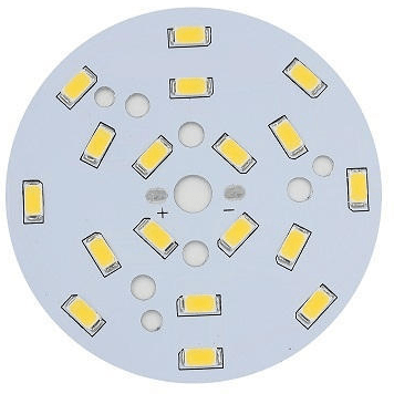
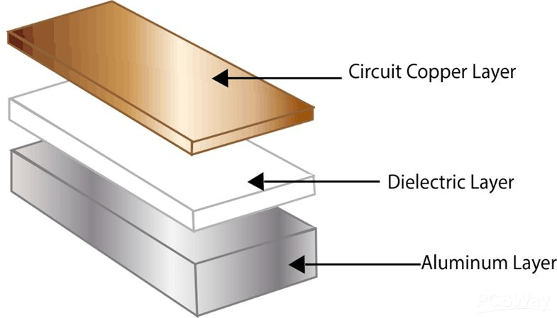
But the boards that are cheap are like the ones above, which have a single layer of copper. In most lighting products, the LEDs are on the aluminum board while the rest of the circuitry is on a separate FR4 board.
Our design didn’t allow for the split board configuration since we wanted to maximize thermal mass and minimize cost. So the challenge was to design a single sided board with all the components needed to provide the functionality. And since all the components were going to be on the same aluminum board, they were going to experience the same high temperature as the LED.
Running all the components at high temperature could shorten their lifespan hence I did a lot of work to validate the design for longevity. The important components, their location and the board size was locked early on the in the design. I set up many tests including longevity testing where the PCB was left on for months. I also set up thermal cycle testing where the PCB would be turned on, allowed to heat up, and the turned off to let cool.
I also had my concerns with the manufacturability of my design so I ordered a small batch of 100 PCBs. That small run revealed good information about the design and component choices. It turned out that one of the component datasheet wasn’t accurate so I had to find an alternative component. I also got good feedback from the factory on how I can improve the design for better DFM.
Now that I had 100 PCBs, I could test a larger sample set and ensure that there isn’t any unexpected unit to unit variation. Well, unfortunately, I did find that the battery indicator chip behaved differently at high temperatures. The threshold voltage I had set for the indicator LEDs would shift randomly at high temperatures between units. I originally suspected a bad batch of chips but after testing samples directly from the manufacturer, I had to find another solution.
There weren’t too many options in the market that I could use given my constraints but I did find one suitable replacement. I tested it in the same conditions as the previous chip, and thankfully, it fared much better. The new chip did require more external components but I was able to move some things around and make it fit.
Manufacturing is Hard
The design was done and we were ramping up towards mass production. But we had terrible luck with finding the right contract manufacturer who was competent enough to do the job and also competitive in pricing. The first one we had been talking to for months bailed on us right as we wanted to ramp, claiming that they don’t feel confident that they can deliver the quality and volume we wanted. That caught us off-guard and we scrambled to find and bring up another CM. But the process was very slow and coordinating everything was challenging.
We were getting late and risking missing even our deadlines. That is when the decision was made to assemble the first batch of lamps in the US while figuring out production in China in parallel.
Lamp Assembly
Assembling the lamps in our office was hard and there were plenty of challenges. But it was a great learning opportunity for me since I had to solve a lot of problems in a very short period of time. At this point, we had received all the parts we needed to get started with assembly including the plastics, PCB, battery etc.
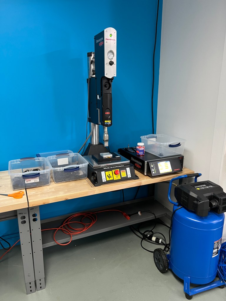
Ultrasonic Welder
The first major issue was figuring out how to ultrasonic weld the top and bottom part of the lamp together since that would require and ultrasonic welder. I searched for where we could buy or rent a machine. Buying would have been very expensive but I found a place that would rent us the machine for a reasonable cost.
After talking to them, I learned that ultrasonic welders operate at different frequencies and require a custom jig and actuator piece (horn) based on the machine. And the machines they use in China operate at a different frequency and have metric bolts for the jig and horn so they wont work on the Branson 2000 (American) welder we could rent. We placed an order with the Ultrasonic machine supplier for the jig and horns but they kept delaying delivery.
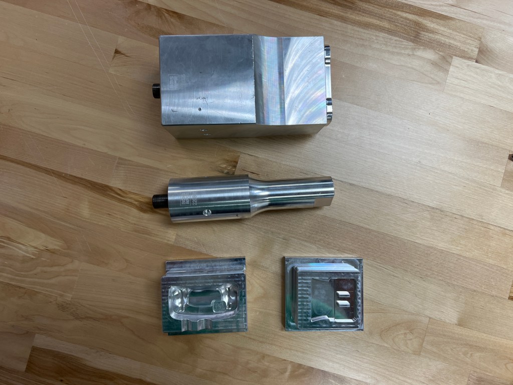
That is when I decided to just go up to their shop and see what is going on. They had a horn and jig made but it was the worst machining quality I had ever seen. And I was stunned because they had an array of Haas CNC mills in the shop. The Chinese horns and jigs that were sent to us were so much high quality in comparison. Regardless, I got the machine, horns and jigs back to our office.
It took a lot of trial and error to dial in the welding process. I had to understand how the horns were working and modify them myself to ensure that the weld would be perfect but the plastic surface wouldn’t be marred. We ended up modifying the Chinese horns and jigs to work with the machine we had instead of using the locally made ones.
Automatic Soldering Machine
The battery terminal in the lamp PCB were designed to be soldered on to avoid the BOM cost of a connector and reduce electrical losses. That would make for a robust design but increase complexity of assembly. We tried to manually solder the battery but the aluminum PCB had a high thermal mass so it was taking way too long.
That is when I remembered seeing an automatic soldering machine on Instagram and thought it might be the solution to our soldering problem. I browsed through Alibaba and surely enough, I found this machine.
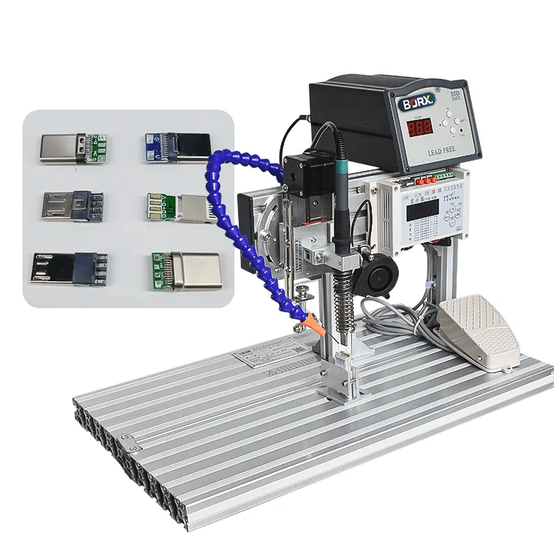
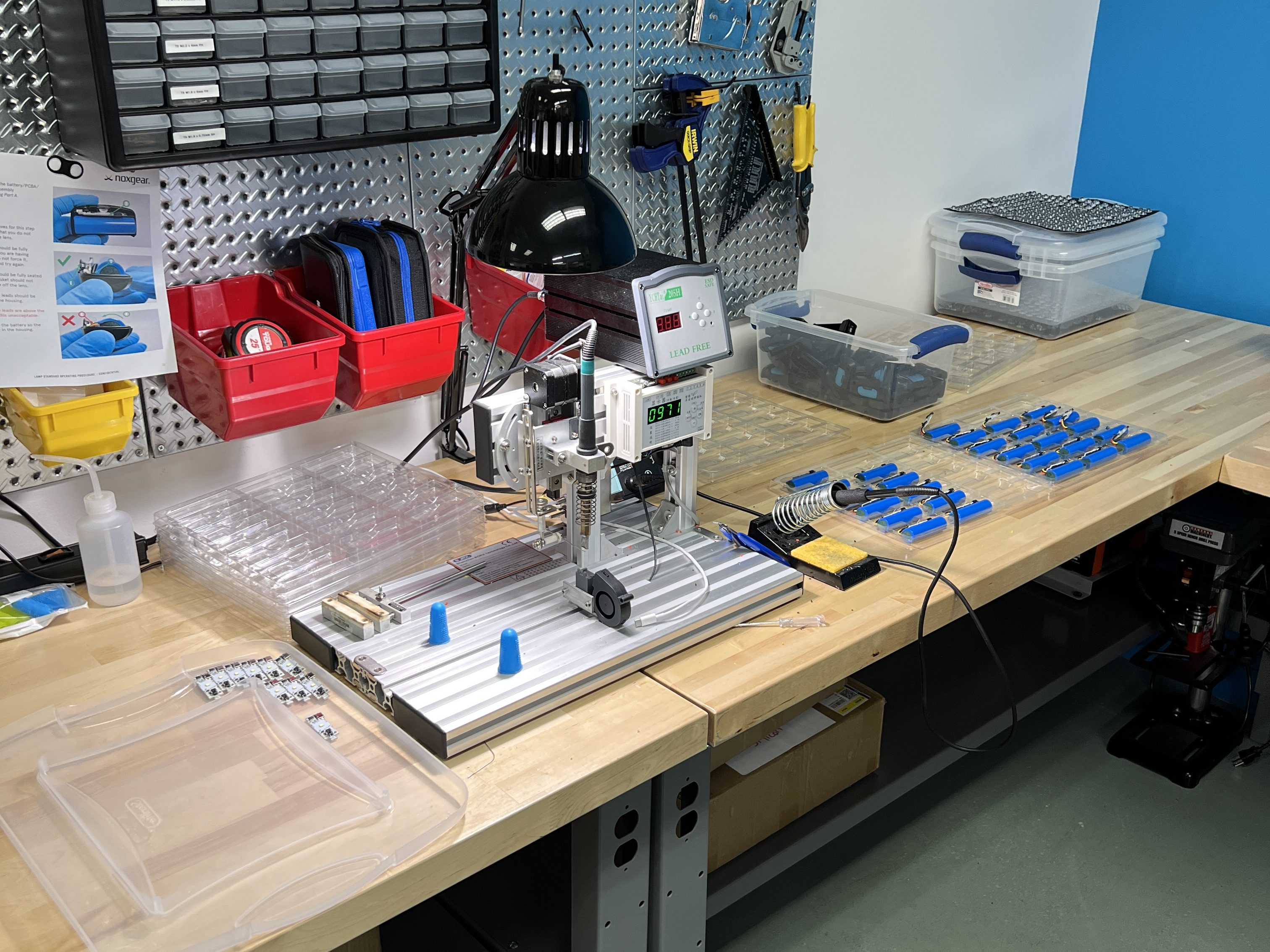
I ordered it and when I received it, I was thinking that with some basic setup, I would be able to solder the PCBs quickly. In reality, nothing is that simple. The machine has a lot of parameters that needed to finely tuned for maximum reliability.
I designed a custom jig to hold the PCB and wires in. That made the alignment process very quick as the wires were held at exactly the right location for soldering. I was able to get pretty quick although solder bridging was a constant problem that would happen every now and then. That was primarily due to the solder pads being closed to each other.
I got good at operating the machine and was able to do upto 1000 soldering joints per day. That allowed us to quickly assemble thousands of lamps over the course of a few weeks.
Assembly Line
The assembly process had quiet a few steps so we set up an assembly line at the office. We asked everyone to help and in true startup fashion, were able to pull everyone together and crank out almost 500 lamps per day.
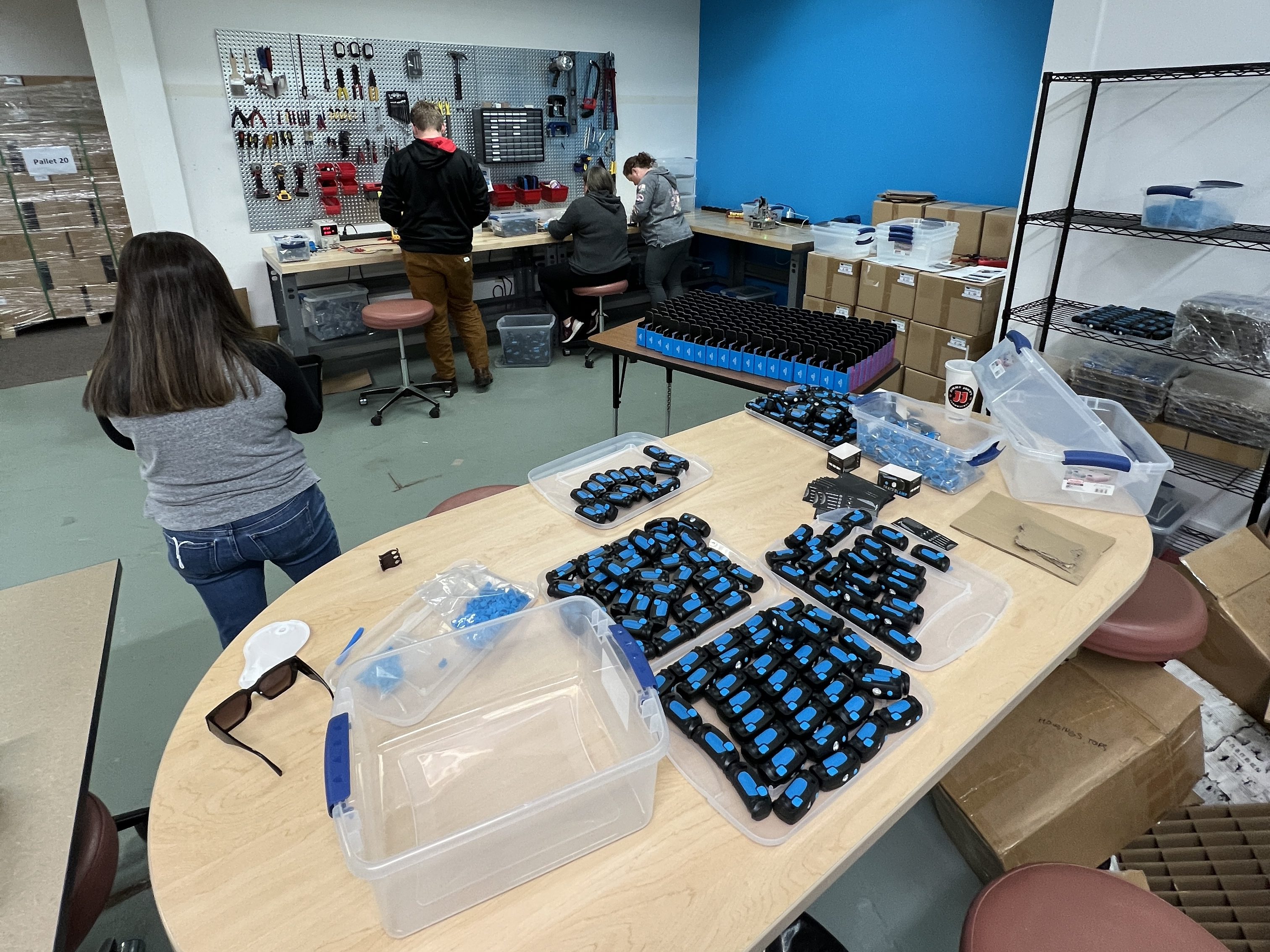
It was a true team effort and despite the setback we faced, we were able to start shipping the lamp before our deadline. Our parallel effort to bring up a new CM in China also panned out since we weren’t under pressure to rush the process. They were able to take over and supply enough volume to fulfill our holiday sale projections.
Conclusion
The Tracer Lamp was a fun and interesting product design journey, one that taught me a lot of important lessons. I am much more confident in my ability to design and ship a product. I hope I can leverage the things I learned to make even better designs in the future.
I hope you enjoyed reading about my design journey with the lamp. Feel free to ask me any questions. Thanks

Leave a comment