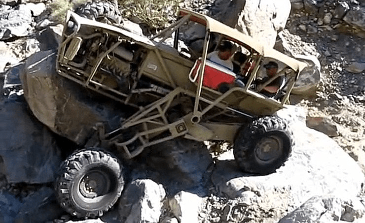
All Terrain Rover
2019-2018

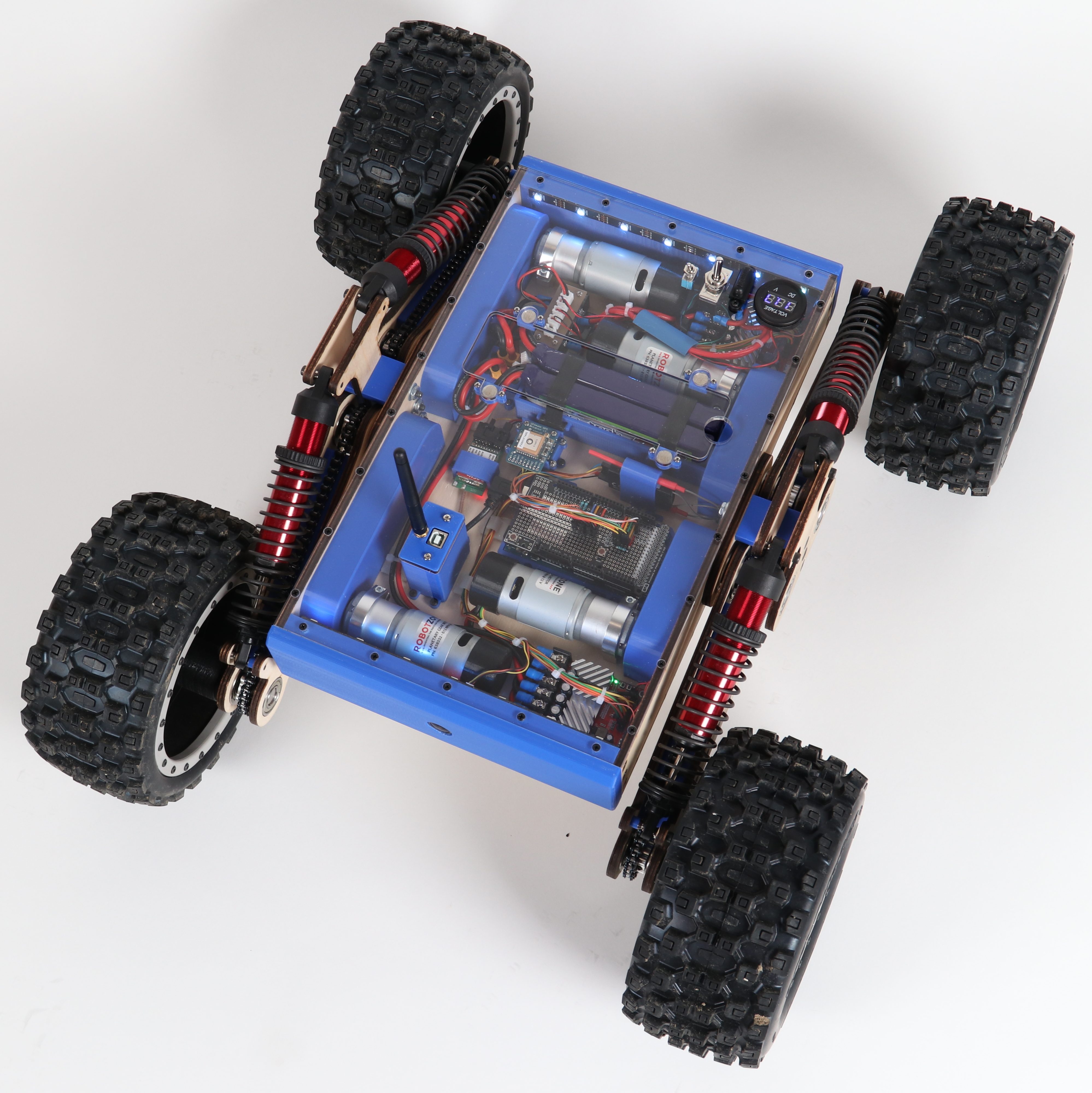
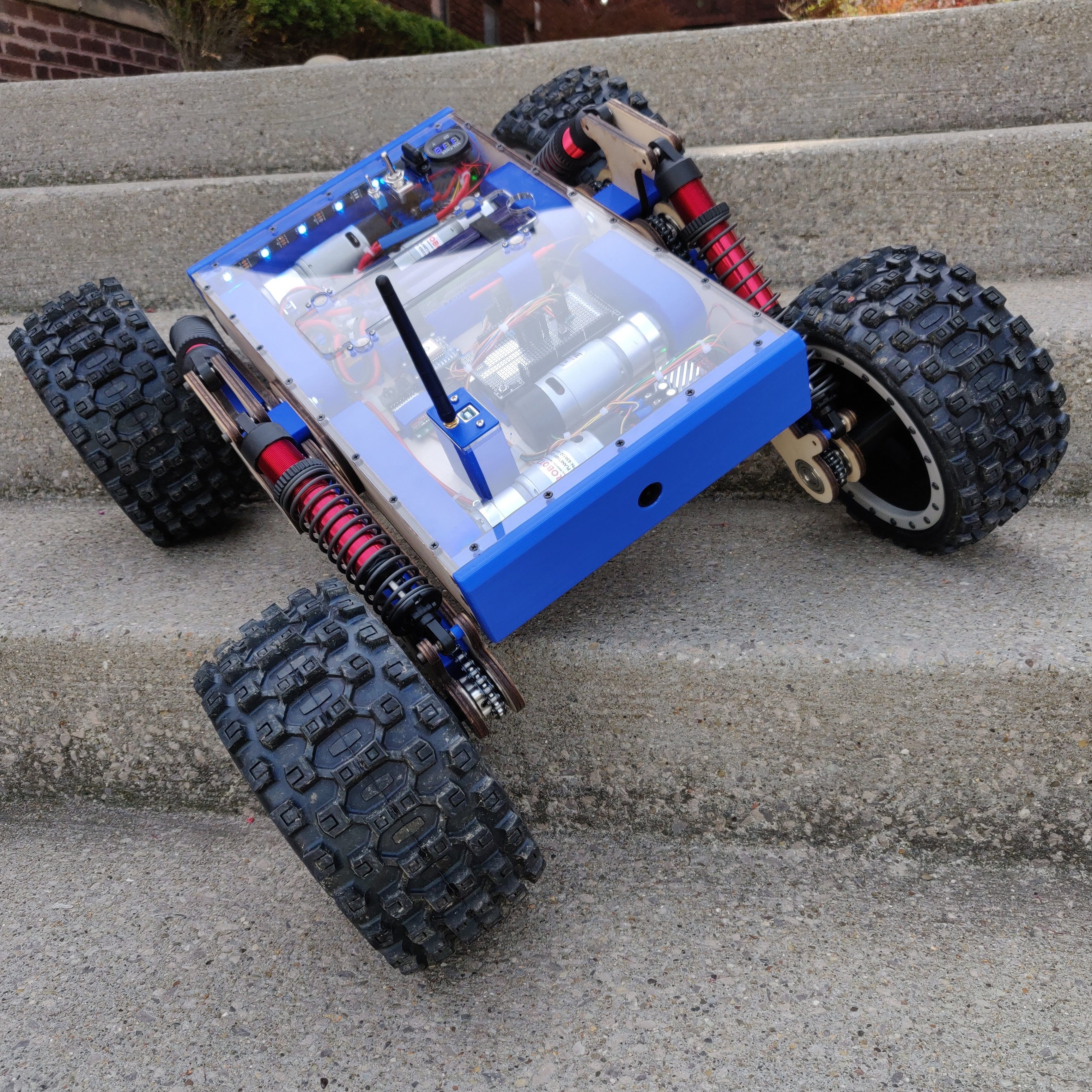
The All Terrain Rover is a 4 wheel drive off-roading monster that can conquer the toughest of terrains with ease. It is built to be a high capable robotic platform that can go anywhere it wants regardless of the terrain and obstacles in the way. The design is fully custom and packs a lot of features in a compact package.
- 4 wheel drive with each wheel having its own motor
- Independent chain drive suspension with large suspension travel
- 8″ Proline Badland Wheels
- Compact, weather-proof chassis with all electronics protected from the elements
- Integrated camera and video transmitter for FPV operation
- Sensors including GPS, IMU, temperature, battery level
- Remote control and autonomous control interface
I will dive deeper into the conception, design and build process of the All Terrain Rover. I will also go over some learnings from the project and potential next steps. I wont be including a build guide since the project was very experimental and there are things I would want to improve on. But if there is enough interest, I can share the design files and add a basic build guide.
Project Links
Github: Code
Background
I love robots and I also love off-roading. I am fascinated by how off-road vehicles can navigate through rugged terrain. I wanted to combine the two and build a robot that can autonomously navigate through rugged terrain, all by itself.
With that goal in mind, I did a lot of research on what already exists and what type of robot I could build. Turns out, not a lot of all terrain robots exist that can go over a wide variety of terrain. There are plenty of tank drive robots but I wanted to make something with wheels. This article caught my eye where someone built an articulated suspension off-road vehicle.
I was impressed by its capabilities and wanted to replicate that on a small scale with some added smarts to make driving the robot much easier. The eventual goal was to make an autonomous robot but I broke the problem down into two parts, the base with all the drive components and the autonomous module with all the sensors and smarts to navigate the robot autonomously. This project only covers the first part of that problem since I never got around to the second part.
Part Selection
Many of my projects start off with an idea in my head that I then sketch or CAD up to see what it would look like and then take it from there. This project started with me searching for parts and building up the concept with certain parts in mind. When I started this project, I knew that I really wanted to use the Proline Badland Tires. They have a very aggressive tread pattern and they just look amazing.


I got the tires and then searched for the other main components. I selected the motors, motor controller and battery. I did some napkin math to make sure I would have enough torque to drive the rover. These main components drove the size and shape of the rover.
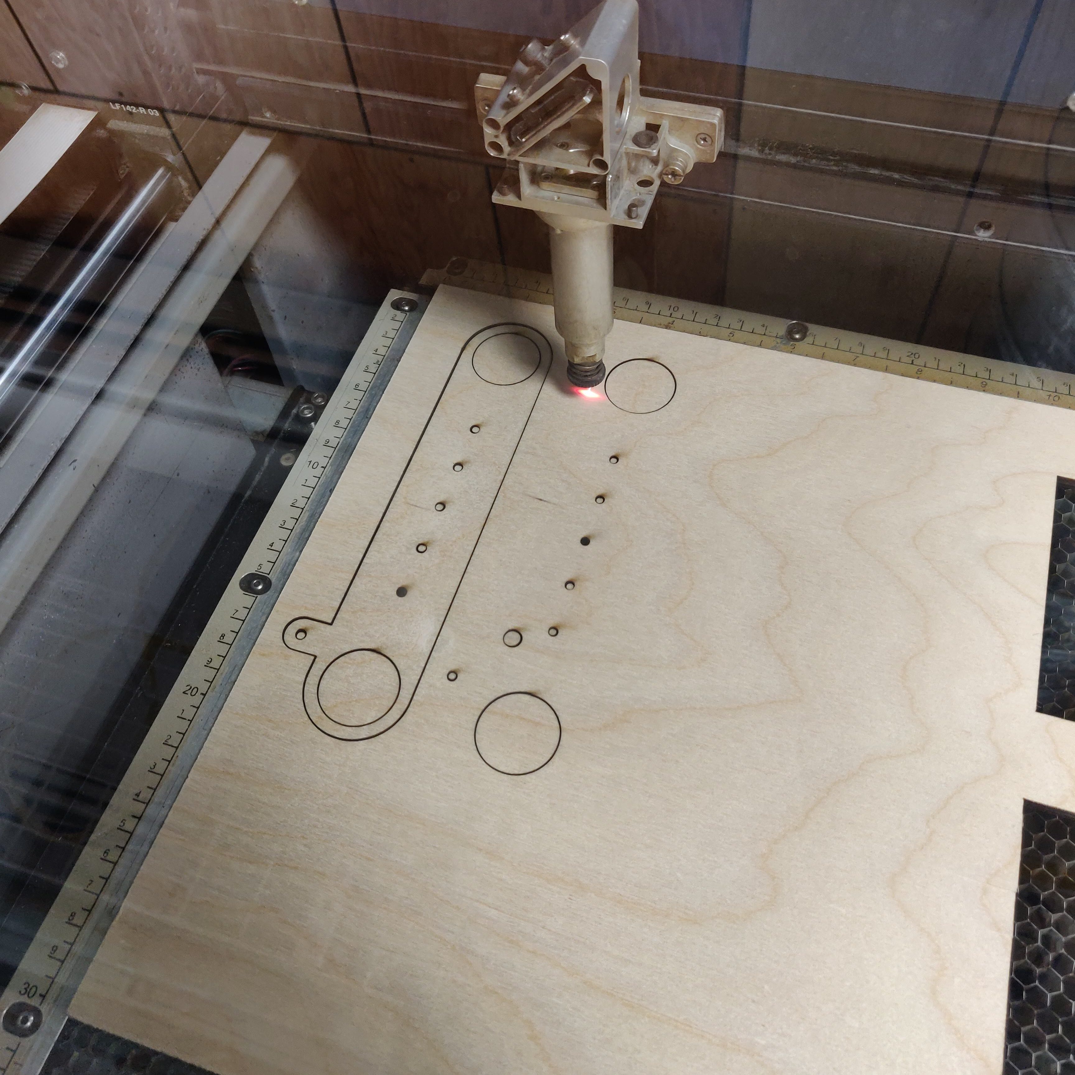
The design was going to be very experimental so I wanted to use prototyping materials which would be quick and easy to work with. I had access to a laser cutter and 3D printer so I designed the rover to utilize those machines. The automatic nature of the two machines allowed me to quickly iterate and modify the design.
Parts List
Here are some of the key parts used in this project.
- Pro-line Racing 1/5 Badlands MX43 Tires PRO1013113 – Amazon
- Traxxas 7761R GTX Shocks – Amazon
- Traxxas GTX Shock Springs 1.538 Rate – Amazon
- 313 RPM HD Premium Planetary Gear Motor – Servocity
- Roboclaw 2x30A Motor Controller – Basicmicro
- Turnigy Nano-Tech 3000mAh 3S 30C Lipo Pack w/XT60 – Hobbyking
- Metal Latching Power Switch (Blue) – Amazon
- Metal E-Stop Switch – Amazon
- Panel DC Volt Meter – Amazon
- TS832 48Ch 5.8G FPV Transmitter – Amazon
- FPV Monitor 5.8GHz 40Ch 7″ – Amazon
- RunCam Racer Nano 2 FPV Camera – Amazon
- Turnigy 9X 9Ch Transmitter w/ Receiver – Hobbyking
- 1/4″ x 12″ x 24″ Baltic Birch Plywood – Amazon
Note: I earn a small commission on Amazon purchases made through this post. But rest assured, my recommendations are not influenced by that at all. Any revenue will most likely go straight back into buying some more tools or supplies.
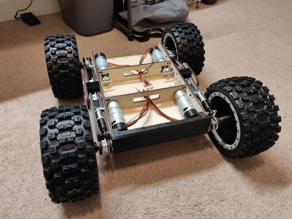
First Prototype
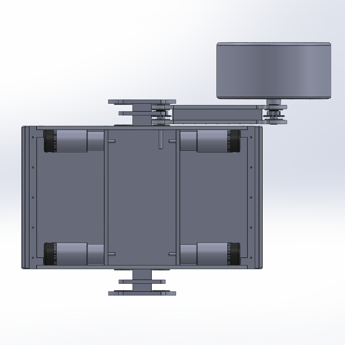
I designed the rover in CAD (SolidWorks) and refined it as much as possible before building a physical prototype. Lets walk through the first prototype design. The main chassis is a rectangular box that will contain all the motors, batteries and electronics. The suspension arms will articulate inline with the length of the chassis, similar to the design inspiration. The wheels would be mounted at the end of the arms and power would be transferred to the wheels using a chain drive mechanism. The motors would be mounted at a right angle to the drive shaft and power would be transferred using a bevel gear.

Forgive the crudeness of the CAD model. I didn’t have time to make it look pretty. I was going for a functional and well engineered design. I was using a pretty slow laptop at the time so I couldn’t load in all the sub-assemblies. I was very excited to test the rover so I didn’t bother refining the CAD and moved on to fabrication.
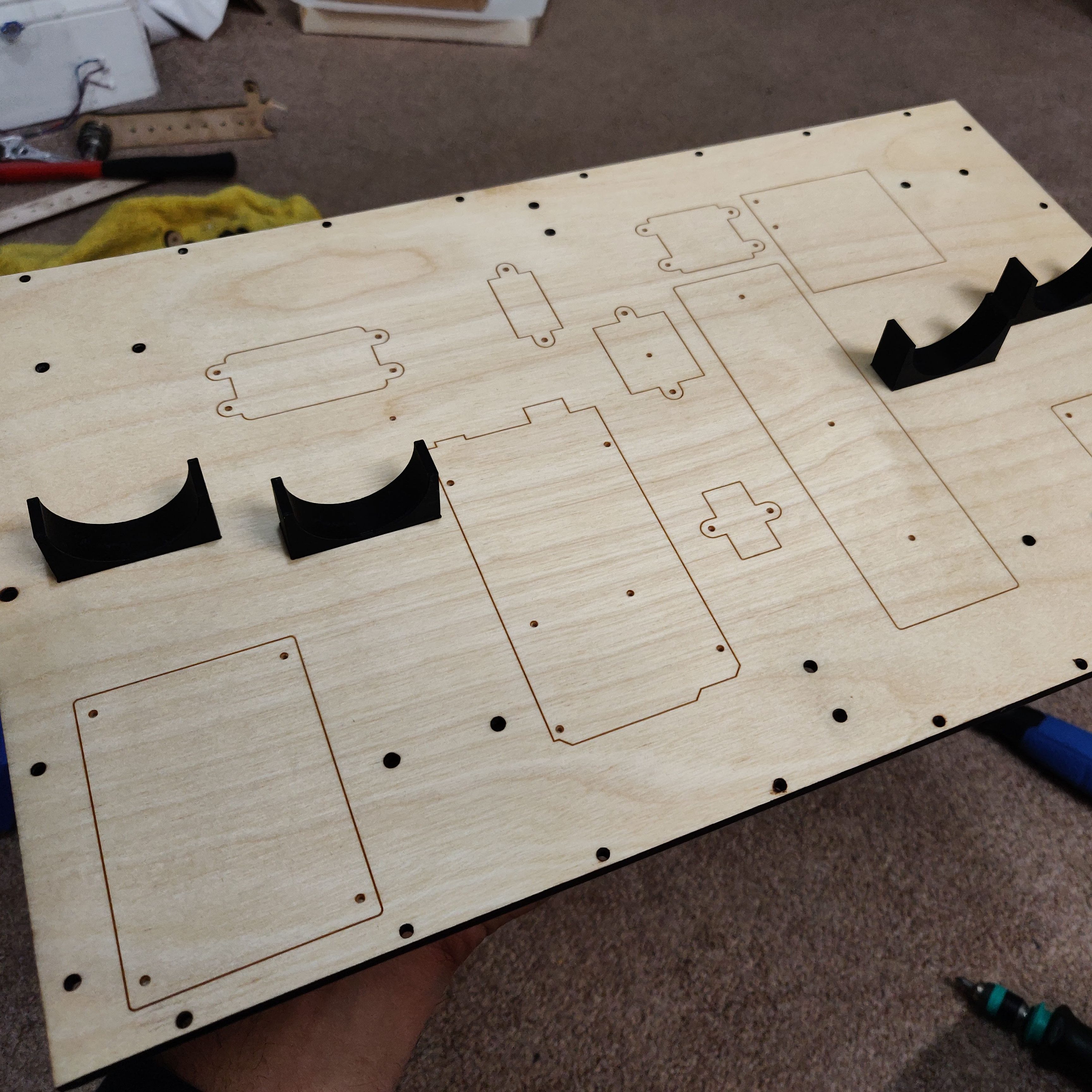
Fabrication
I translated the CAD design into vector graphics that can be cut on a laser cutter. I used 1/4″ birch plywood since that is what I had available and it was an excellent choice for prototyping. Parts which couldn’t be made on the laser cutter were 3D printed like spacers and wheel adapter piece.
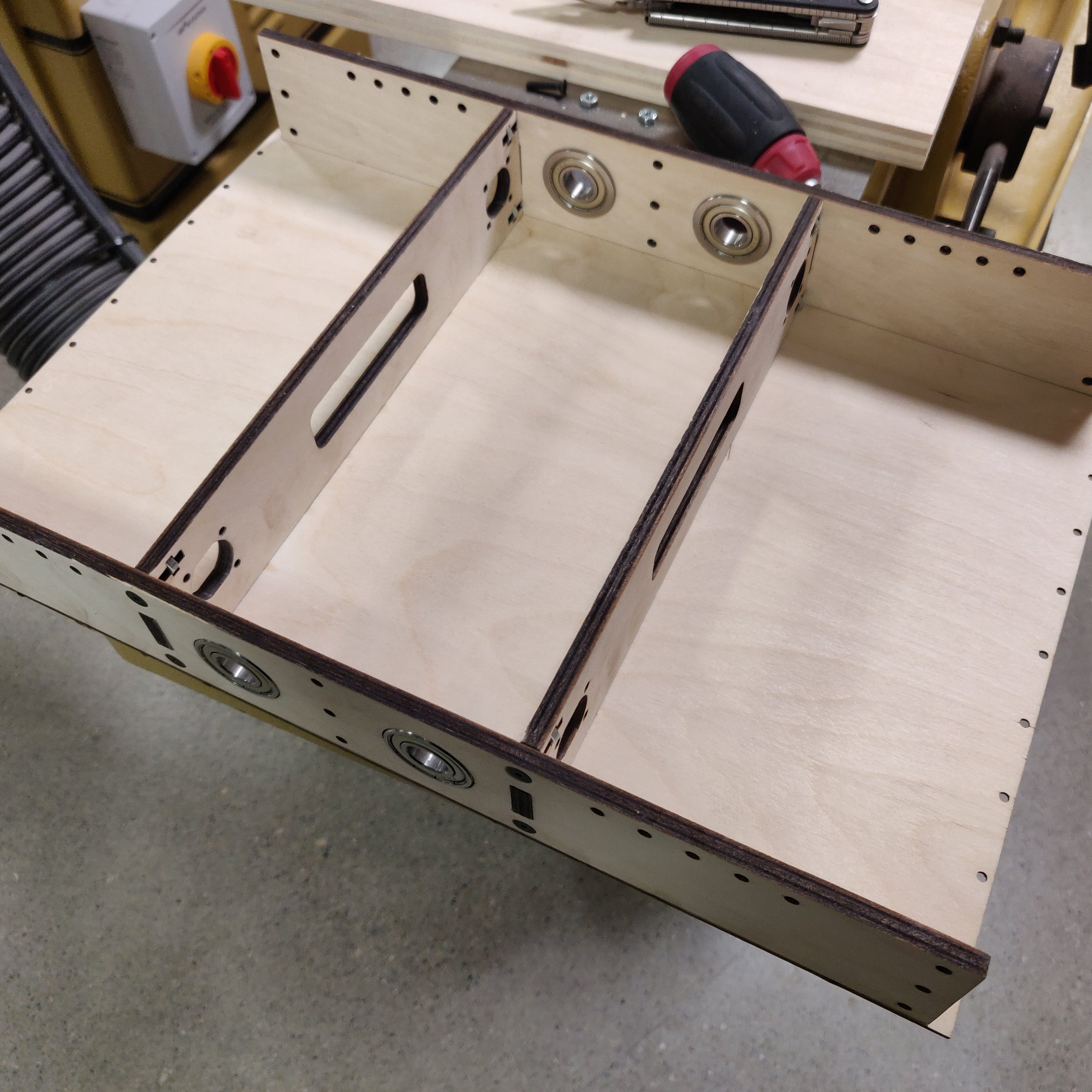
Chassis
You might notice minor design changes in the various pictures and that is because I was quickly iterating through the design and improving it every step I went.
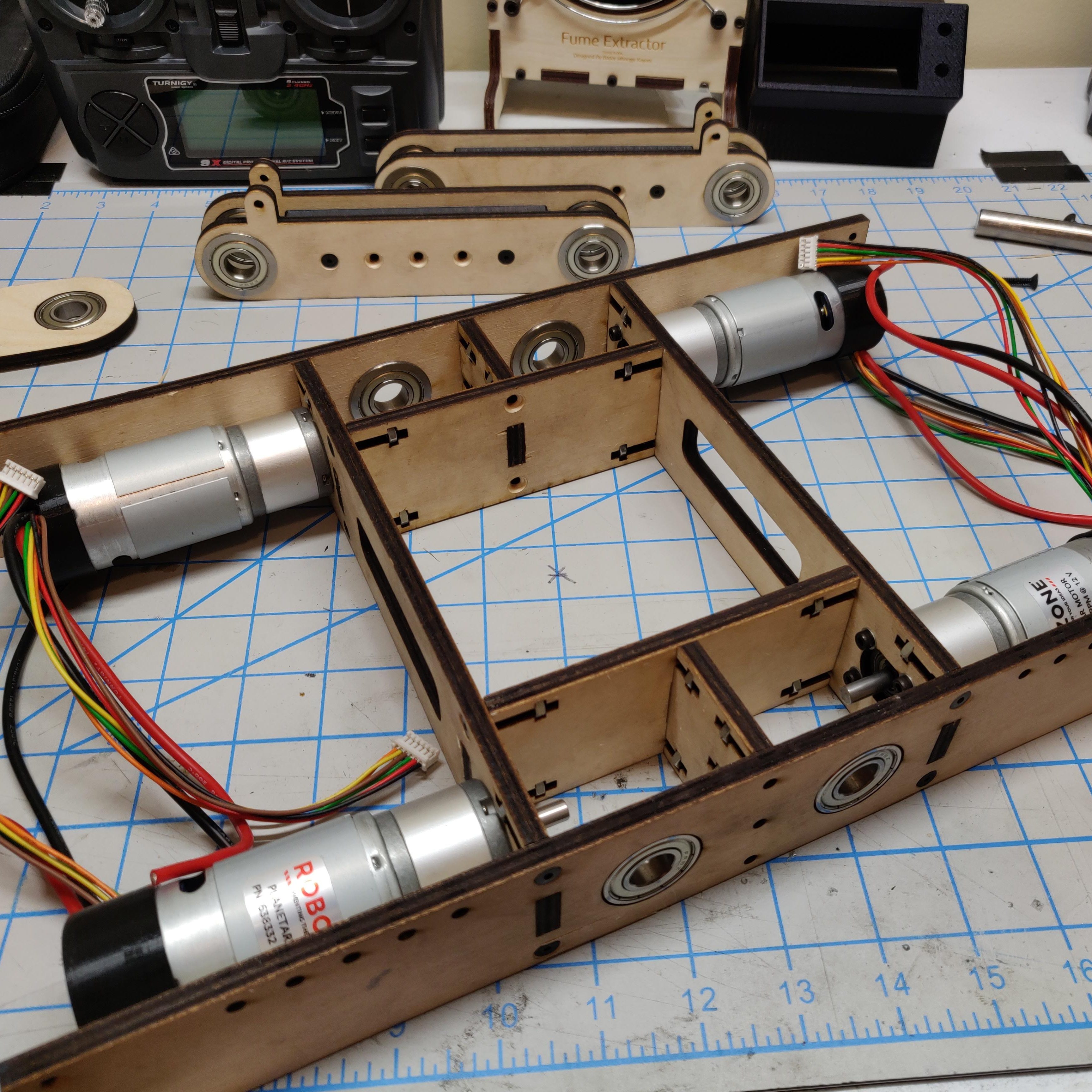
I used captured nuts and screws to fasten the panels together. Slots were added to further strengthen the structure. I soon realized that some of the inner structural pieces weren’t really necessary so I simplified the design in later revisions.

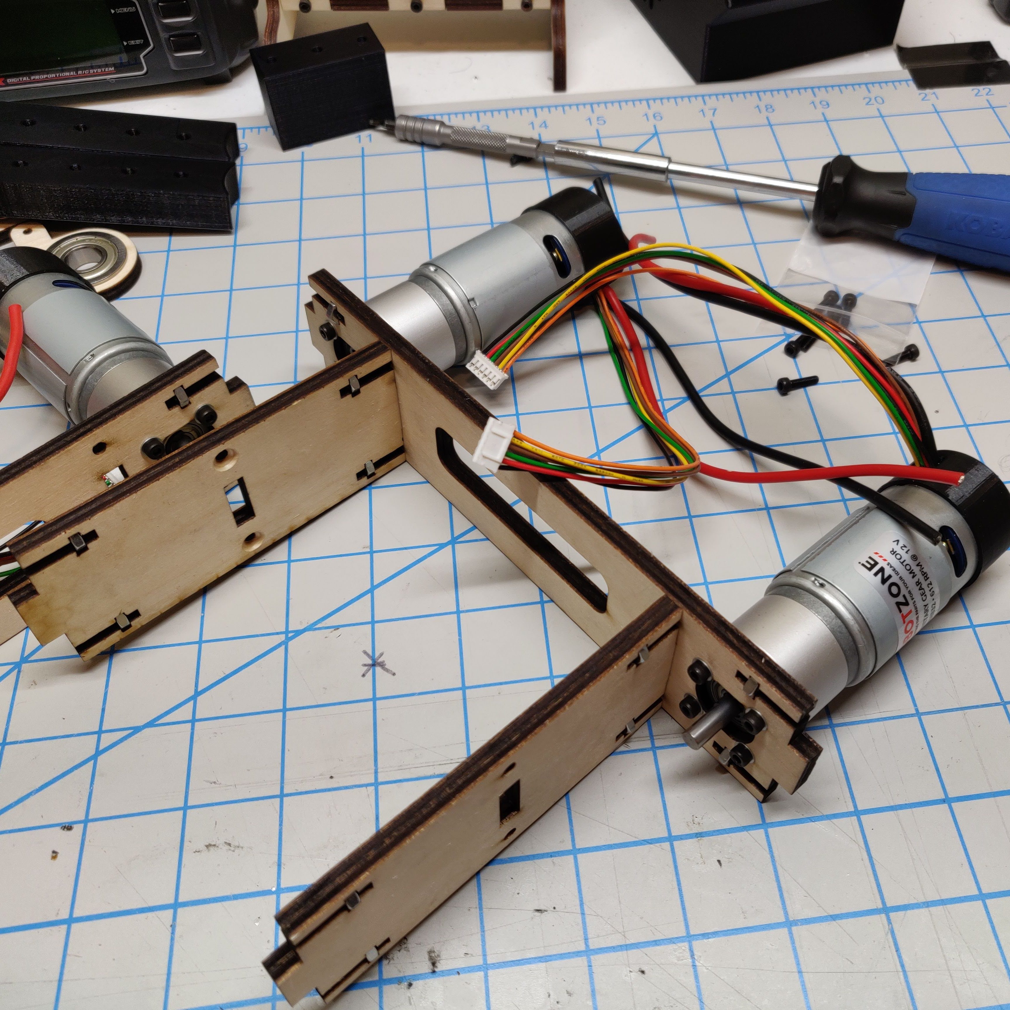
Motors
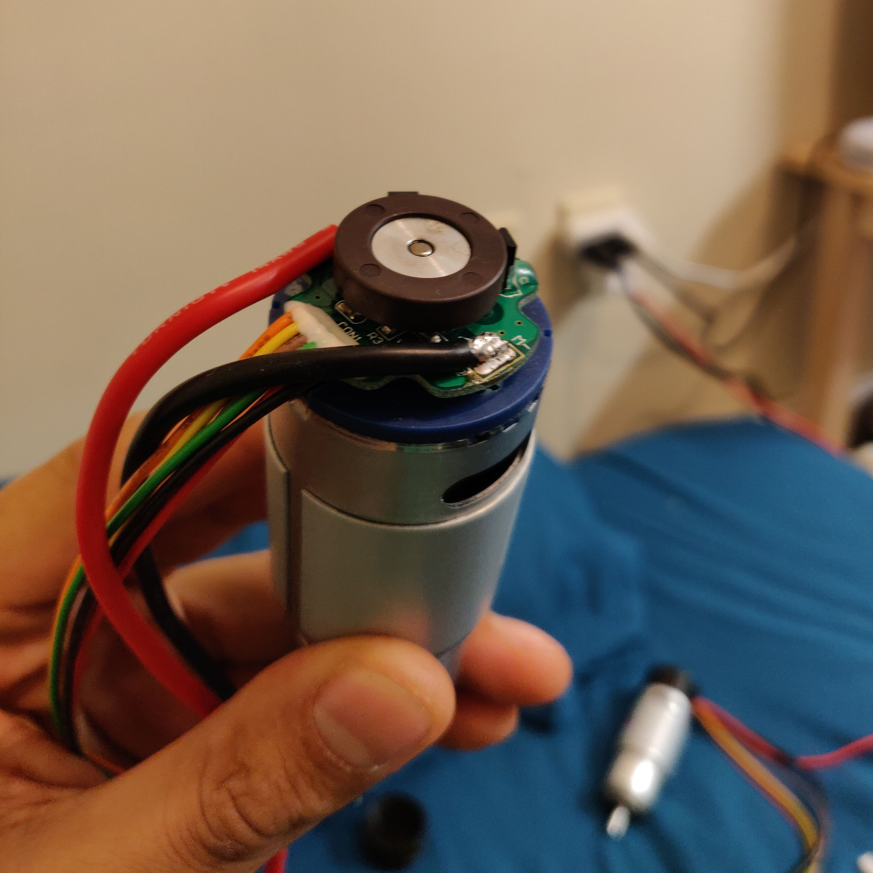
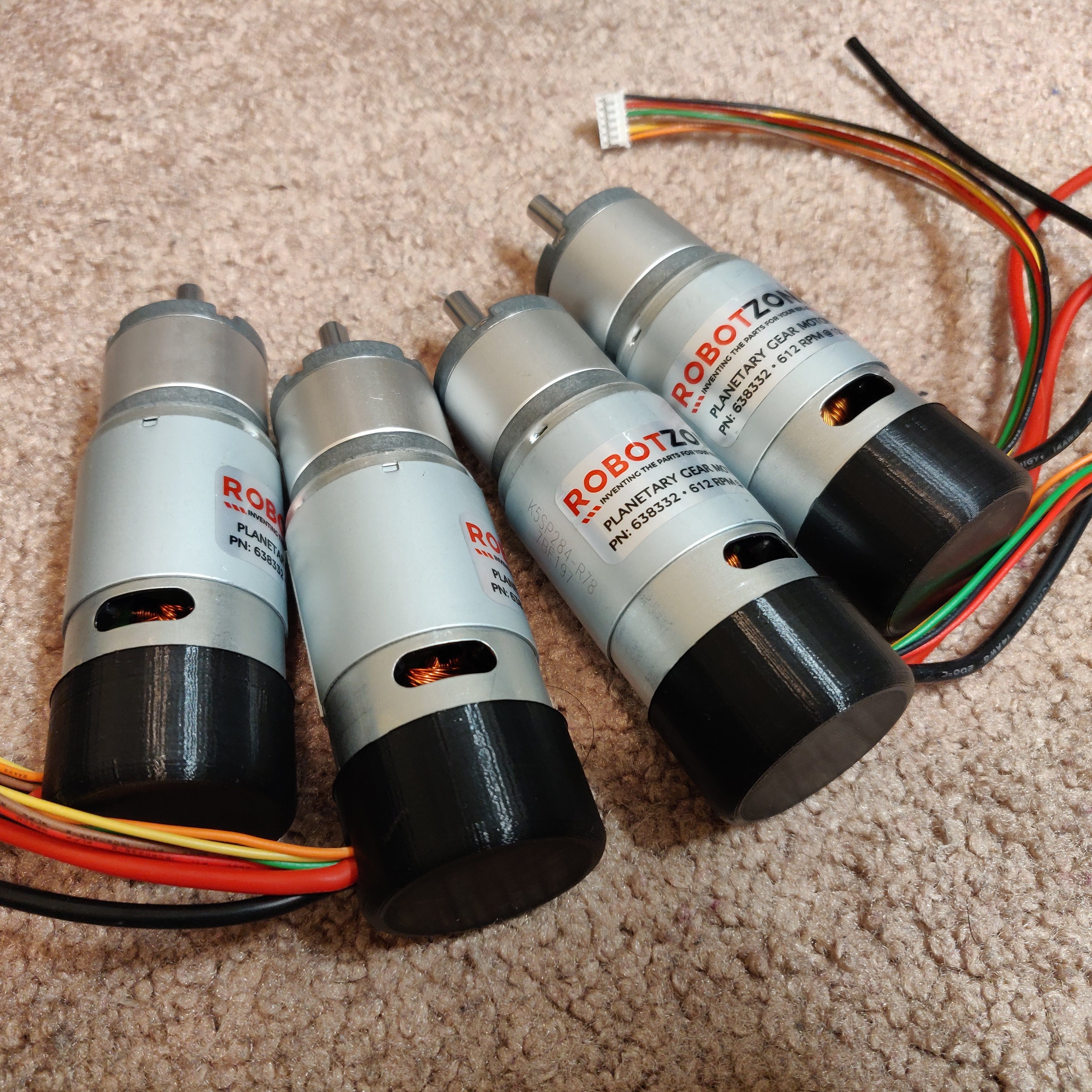
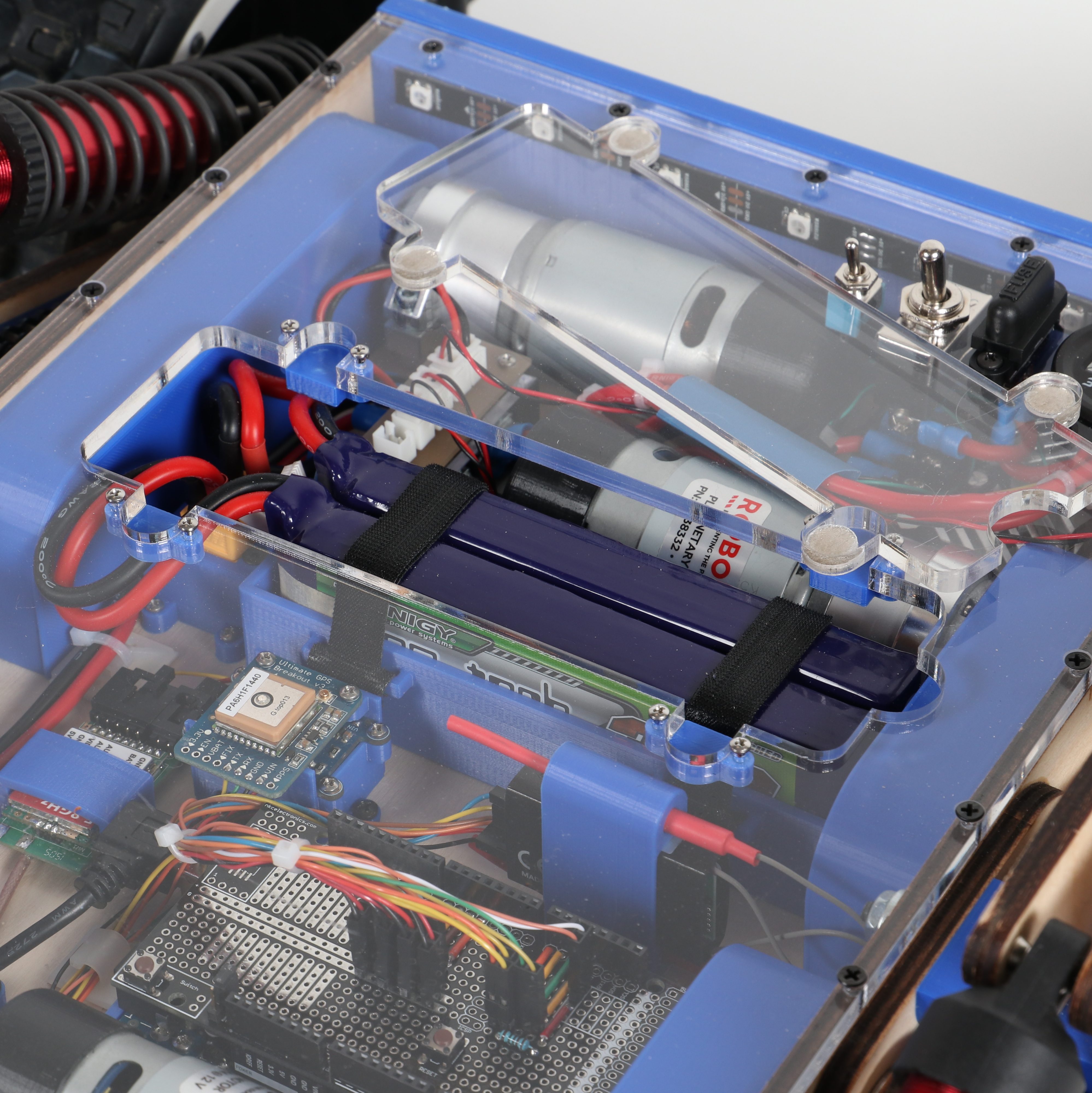
The motors I used were from the HD Planetary Gear Motor series by Actobotics. They came with an exposed encoder assembly and the power leads were quiet thin. I soldered thicker silicon coated wires directly to the motor leads as I knew I would be pushing a lot of current into the motor. I also 3D printed a nice cover to contain the encoder assembly and prevent damage.
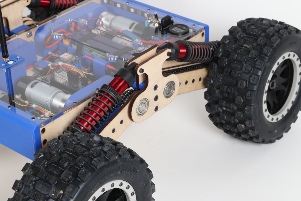
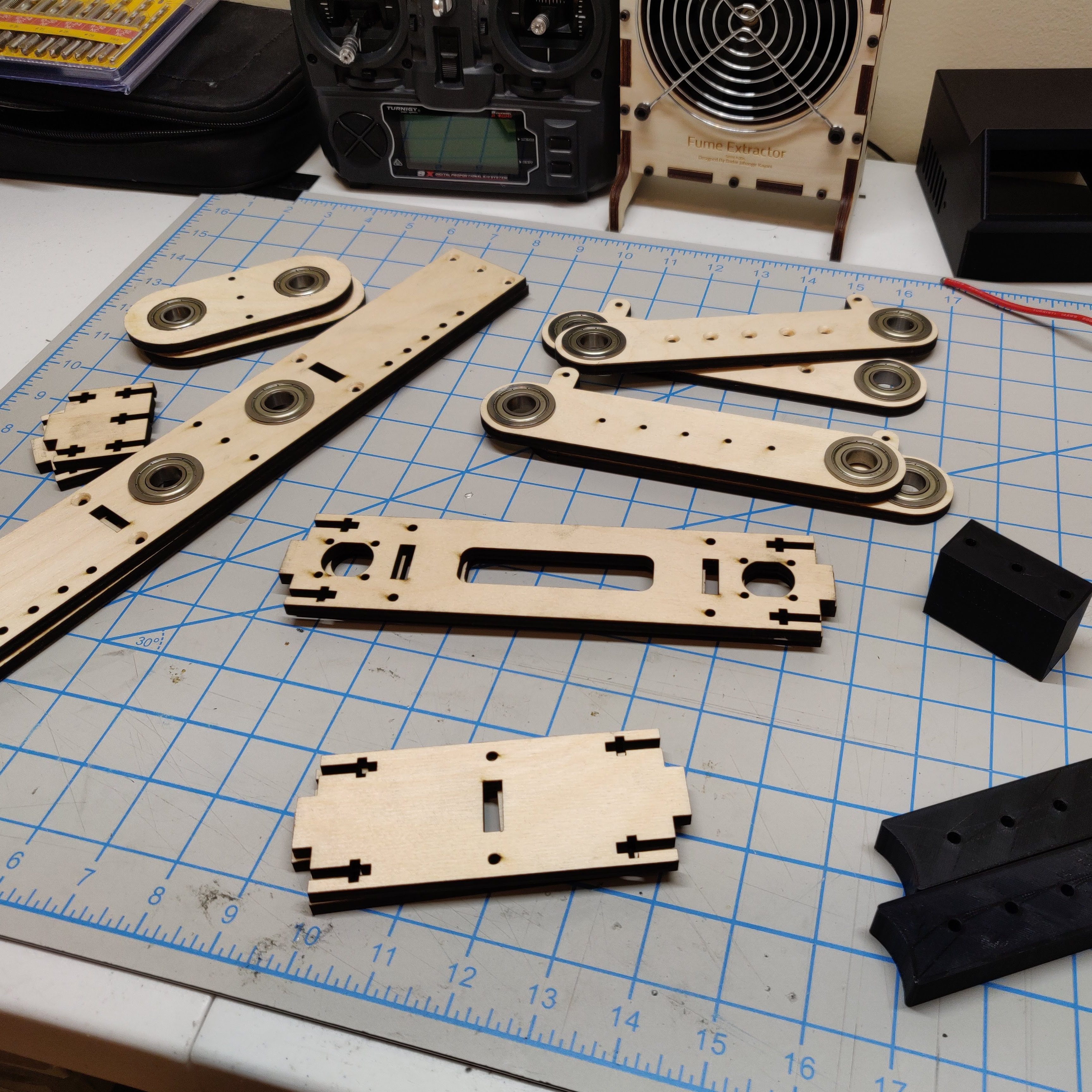
Suspension Arms
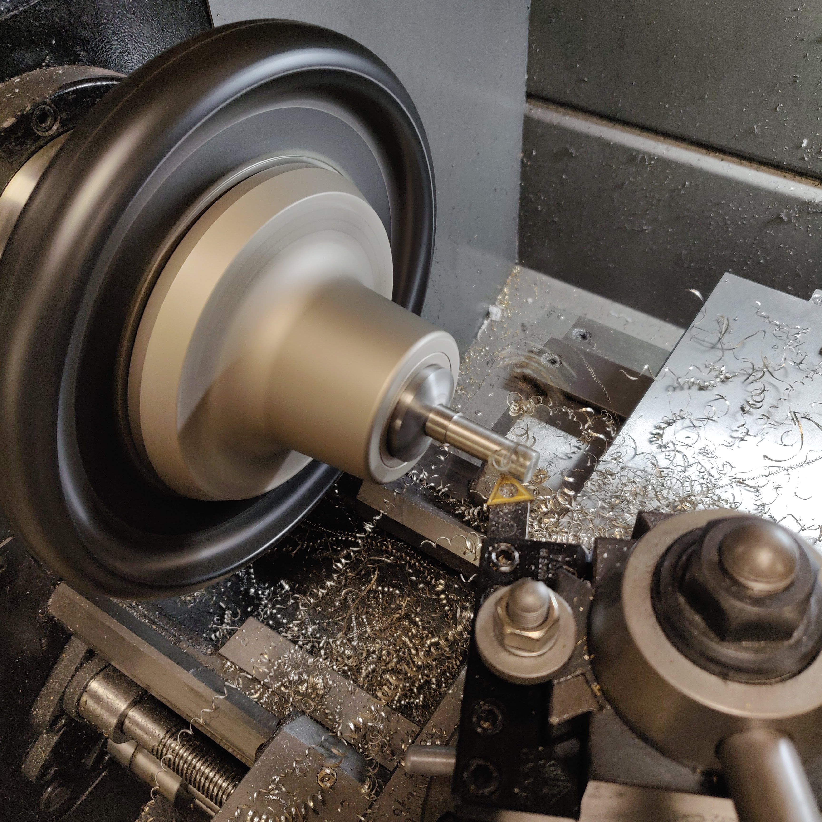
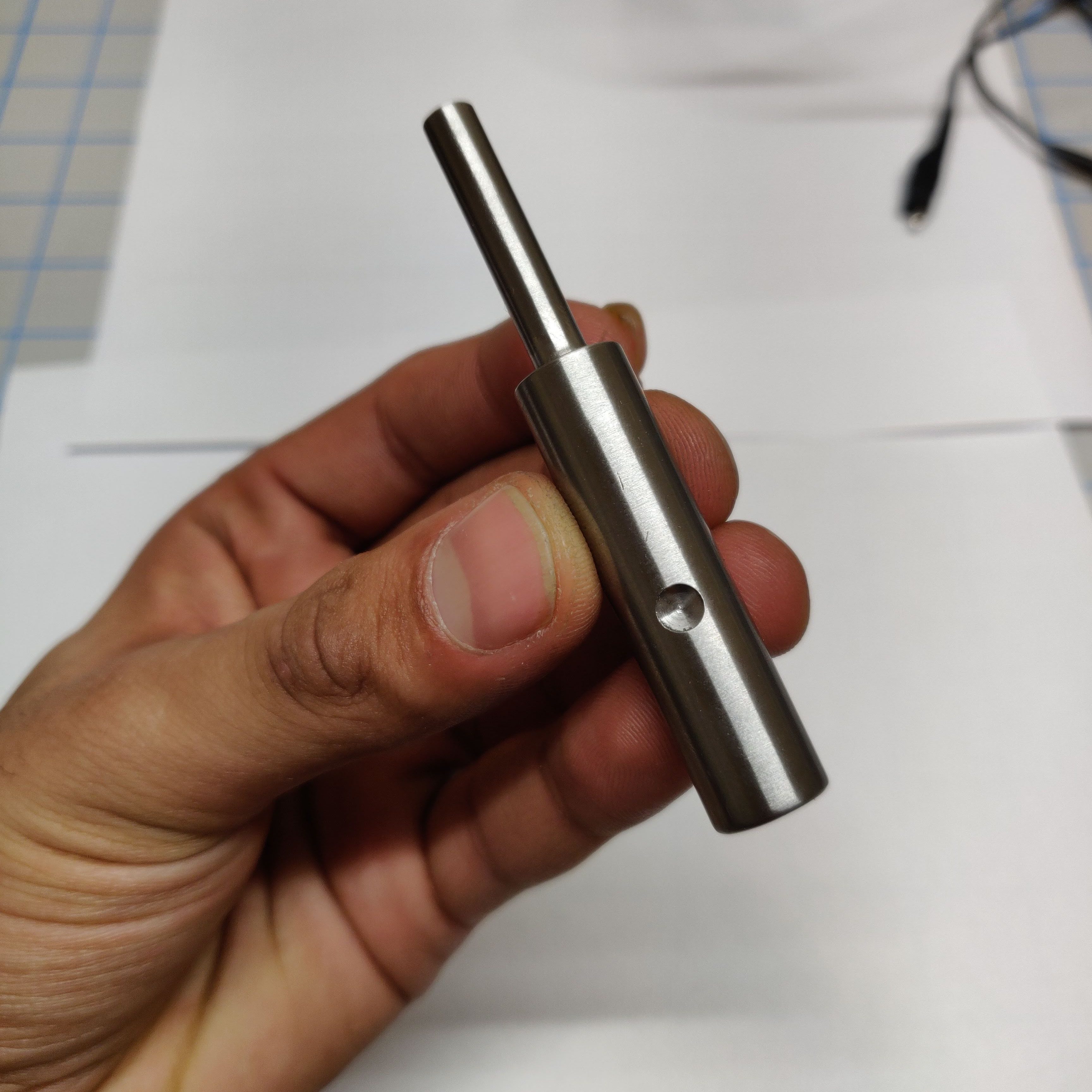
The suspension arm has two drive shafts. The upper one that is being driven by the motor and the lower one on which the wheel is mounted. The shafts needed to be machined to accept the gears and keep them secured. I used the lathe and manual mill to fabricate the shafts.
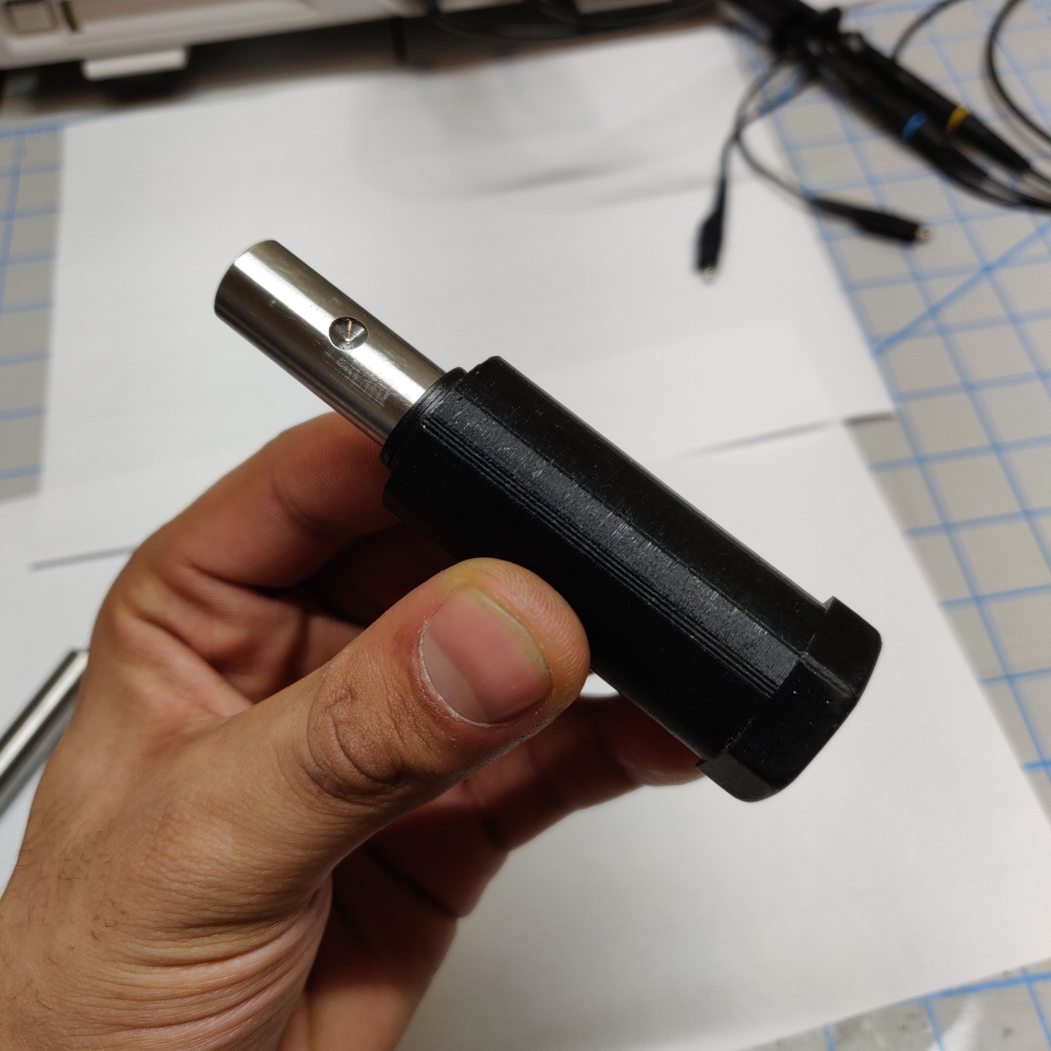
I 3D printed an adapter piece that would secure the shaft to the wheel. This piece had a hex profile on one end that fits into the wheel and a tapped hole for the wheel nut.


The suspension arm is a sandwich of two laser cut pieces and a 3D printed spacer. I am using the drive shaft as the mounting mechanism as well hence the need to have a 0.5″ thick drive shaft. I use bearings on the suspension arm and on the chassis to hold the arm in place and allow the drive shaft to freely rotate.
Shocks
When I assembled the prototype and put on the wheels, I very quickly realized that I messed up on the selection of the shocks. Originally, I selected these small, spring loaded shocks from Actobotics that compressed fully on just the load of the chassis and motors. They were also very flimsy and had a weak dampening action.
I then switched over to considerably bigger shocks by Traxxas. Since the wheels are actually built for the Traxxas X-Maxx RC truck, I figured that the shocks from that truck would work for me as well.


I had to add a shock tower to accommodate the larger size of the shocks but after some CAD and prototype work, I was able to dial in the correct placement that allowed for maximum suspension travel.
I really wanted to have active suspension where I could electronically control the ride height while still allowing for some suspension action. But unfortunately I couldn’t figure out a cost effective way to implement that.
Assembly

I assembled a working prototype of the rover so that I can test it out. Please don’t mind the mess in the background, I was working on this in a very small dorm room.
Testing
I programmed in a basic RC control code and took the rover out for some testing. After about 10 minutes of driving on a variety of terrains, I noticed that the motors were starting to heat up. The bevel gears were also starting to get chewed up.
What I learned was that the motors were not sized properly and I was running them too hard. That is why they were heating up and struggling to keep the RPM up. The gears were made out of aluminum so they were also not handling the power well.
I could have went for steel bevel gears but I realized that the gears require perfect alignment to work properly which my laser cut chassis did not provide. So I switched over to a chain drive mechanism inside the chassis as well. I also got higher geared motors for more torque. These motors aren’t the best for power density but considering the cost, they were a pretty decent option.
Unfortunately I don’t have any pictures from this testing but I will have more pictures for the second prototype. Since I was using prototyping materials, I was able to quickly move to the second prototype.
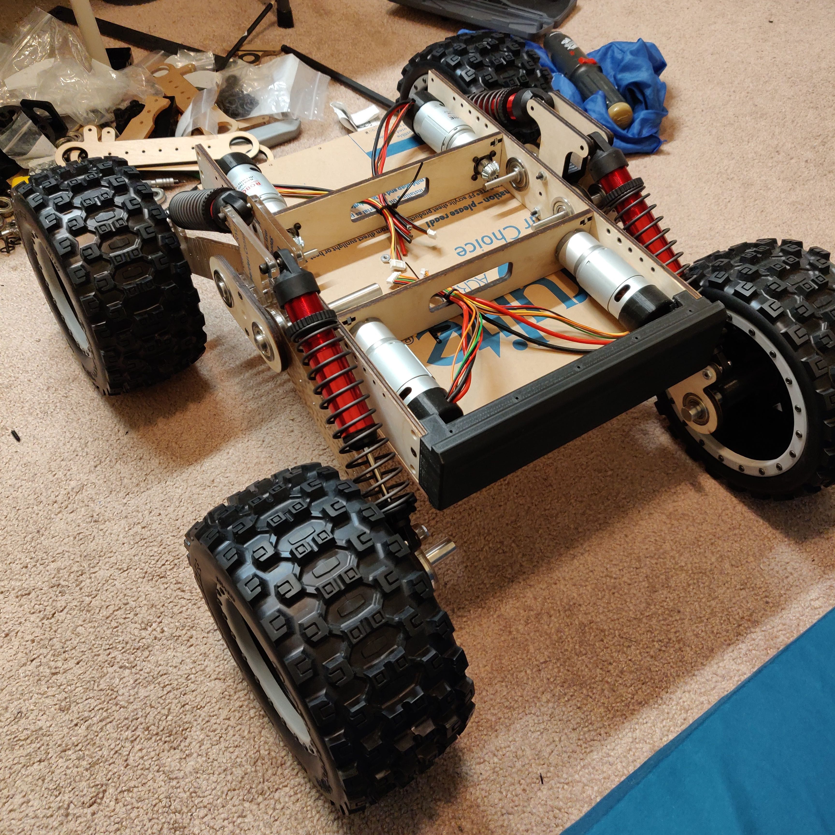
Second Prototype

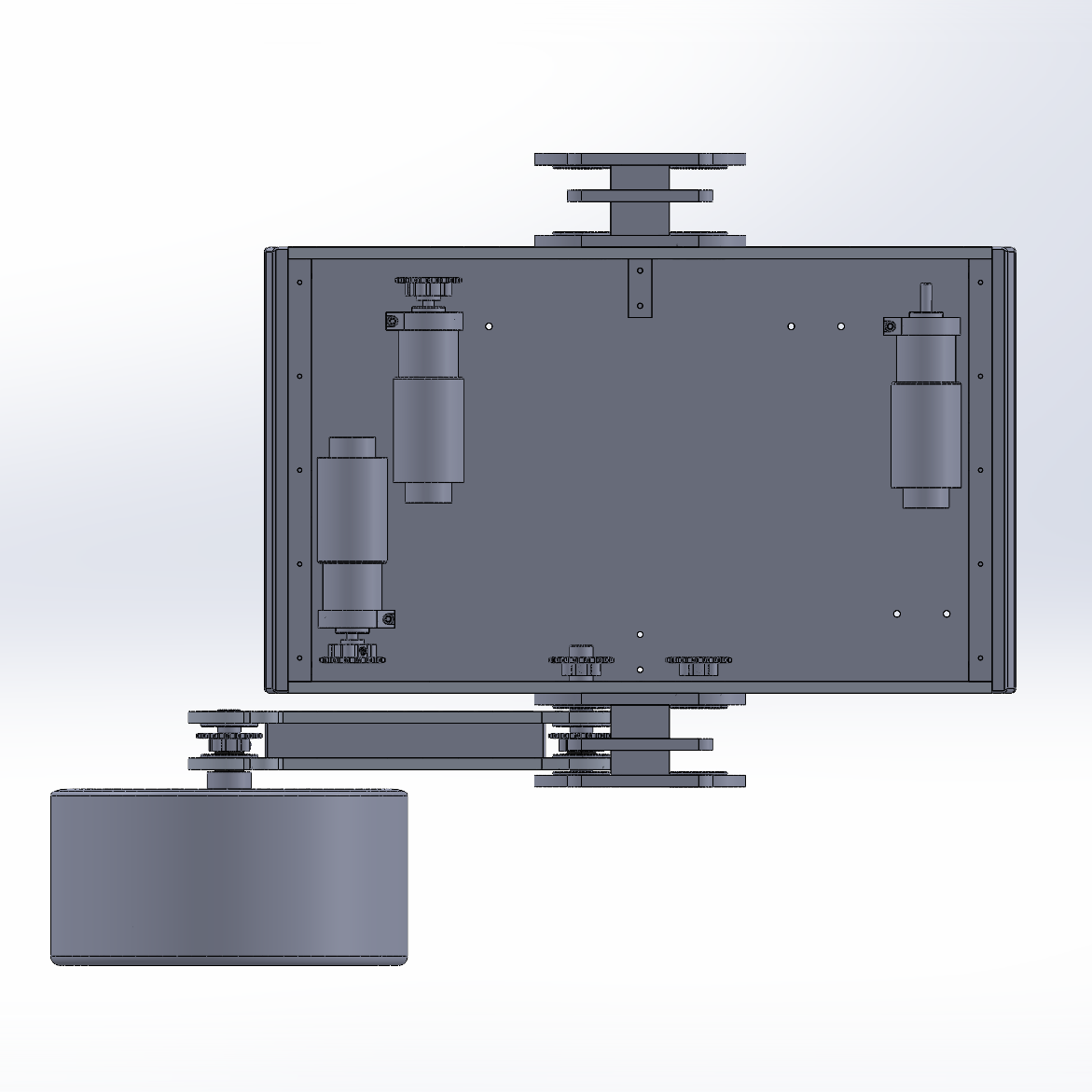
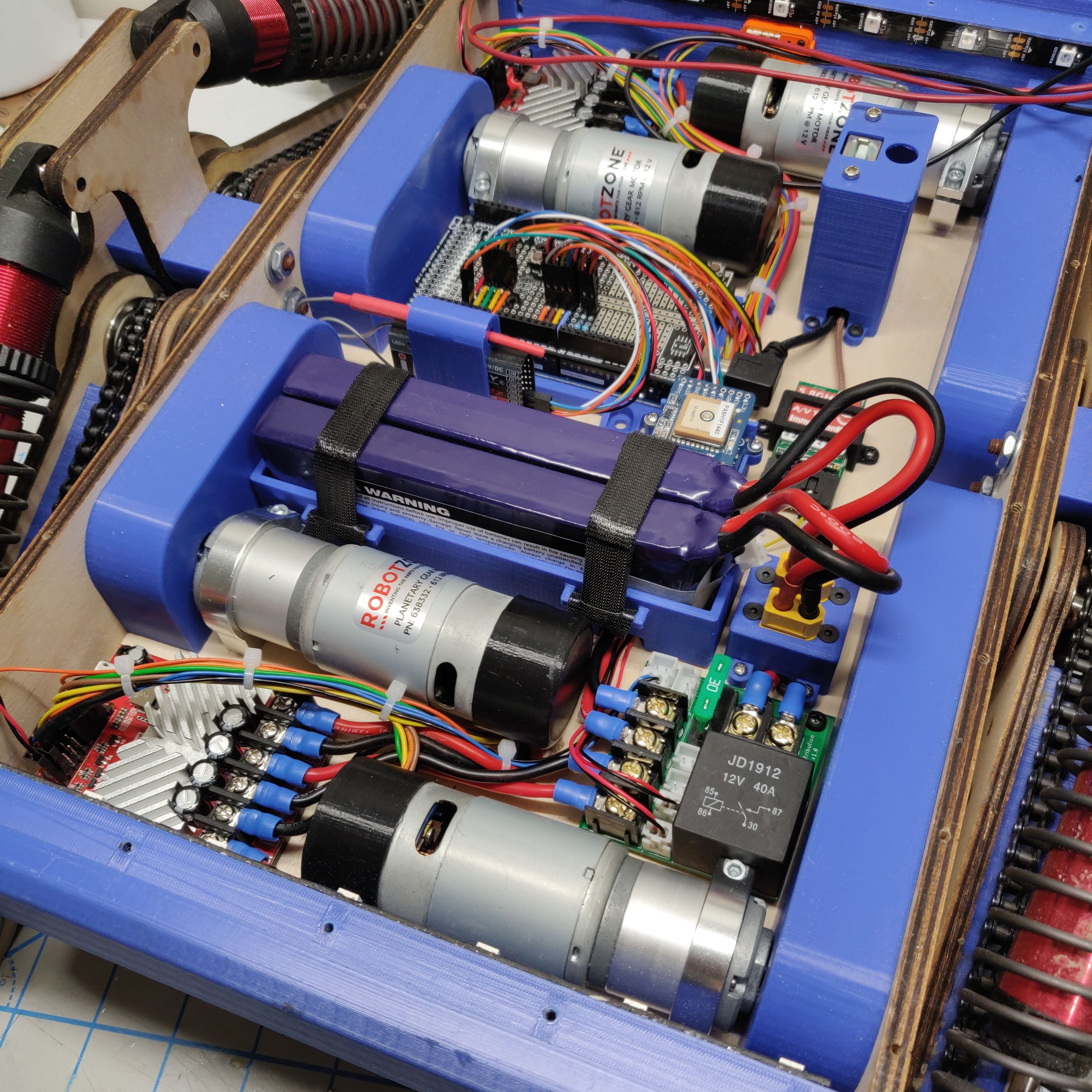
The major update in the second prototype was the change in the motor position and internal layout. To accommodate all the electronics, I had to replace the internal support pieces with aluminum blocks. The focus of the second prototype was more on the internal components.
Fabrication
The design wasn’t very different from the first prototype so I used similar fabrication methods. I had to print a lot of 3D printed parts, some of which are load bearing or will be experiencing thermal stress, so I tried different materials.
Chassis
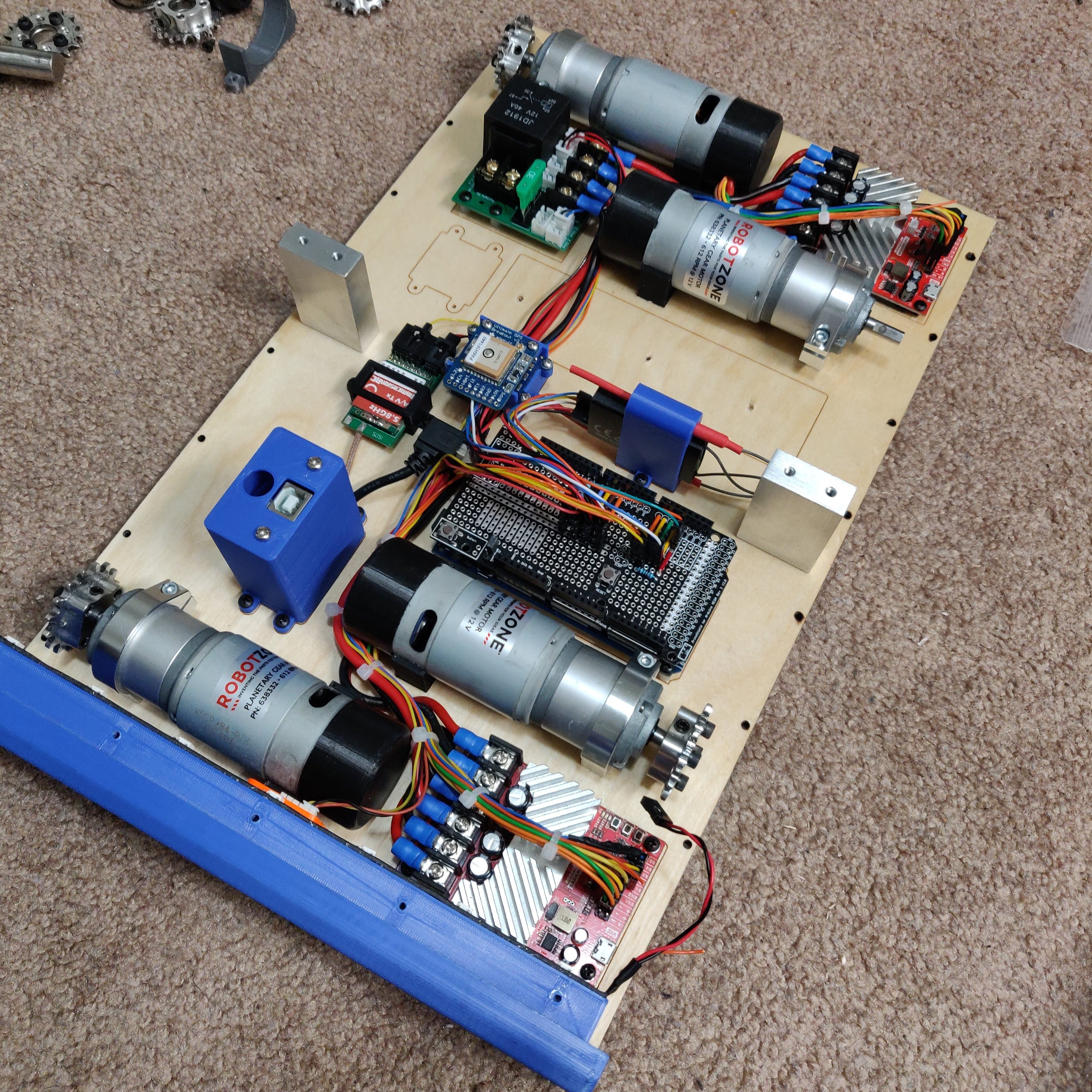
I played around with the internal chassis design a lot and iterated through it to get to this final design. I designed a lot of 3D printed parts to hold various parts in place. The black motor support bracket were printed in ABS and help to keep the motors in place under load.
I put effort on having good cable management as there were a lot of cable running the length of the rover. I used clips to hold down the wiring loom to the chassis and zip ties to keep all the cables together. This made for a assembly that is hard to easily change buy everything was held in place while also looking neat and tidy.
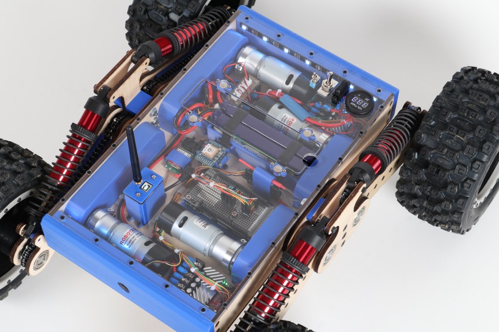
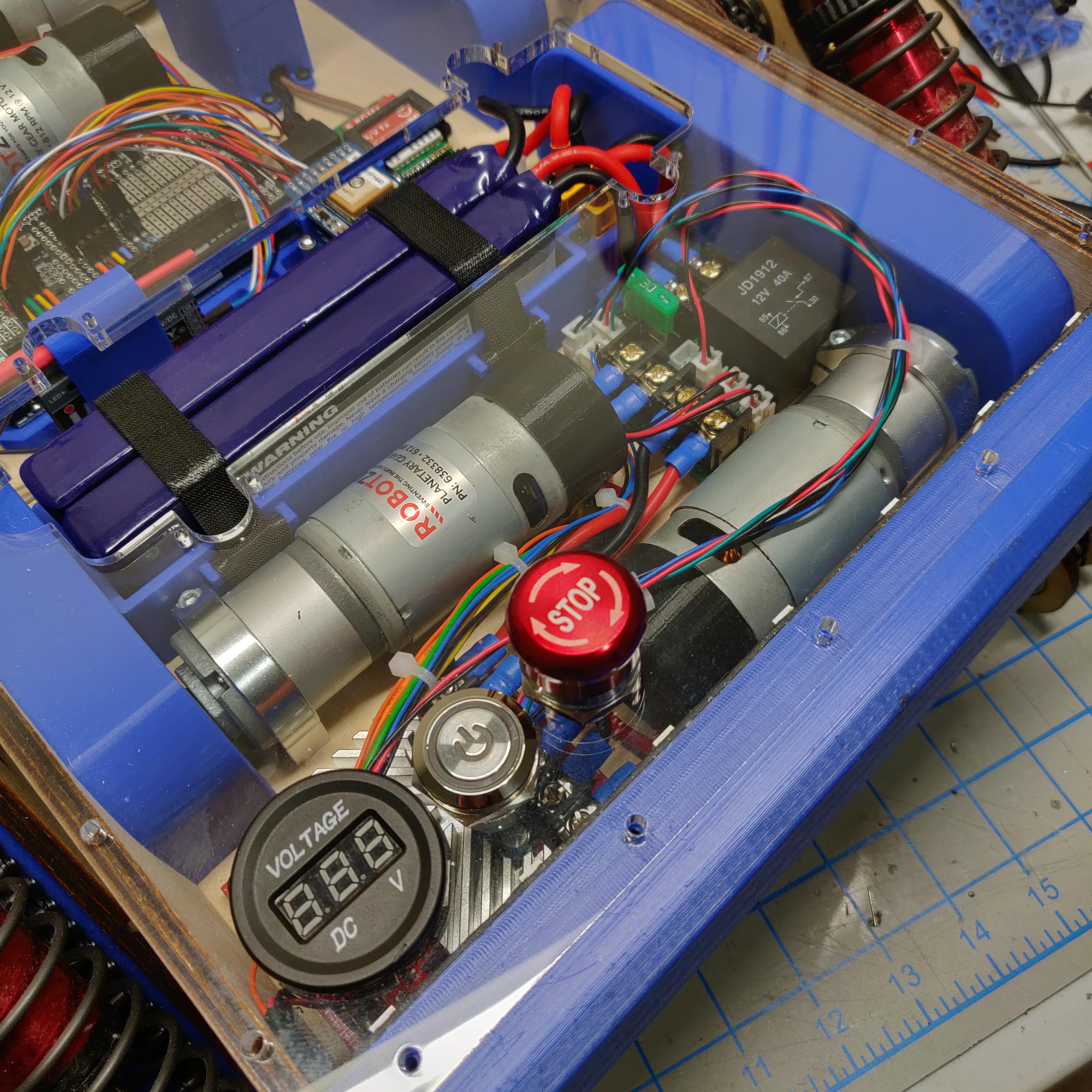
Power Distribution PCB
Originally, I had a terminal block that was distributing power to the sub-modules but that made the wiring messy and I had to wire high current lines to the top cover for the main switch. Hence I designed a simple PCB to distribute the power.
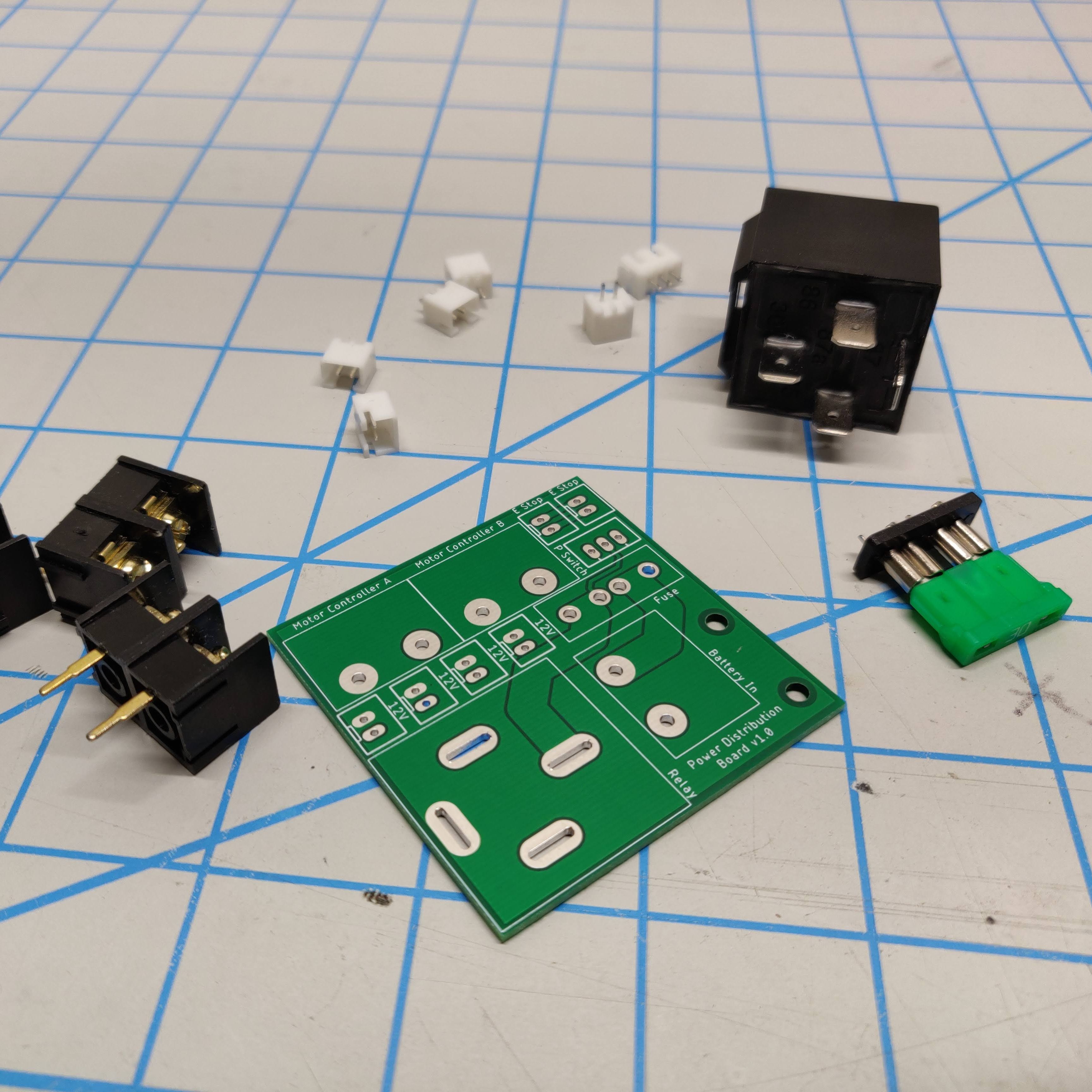
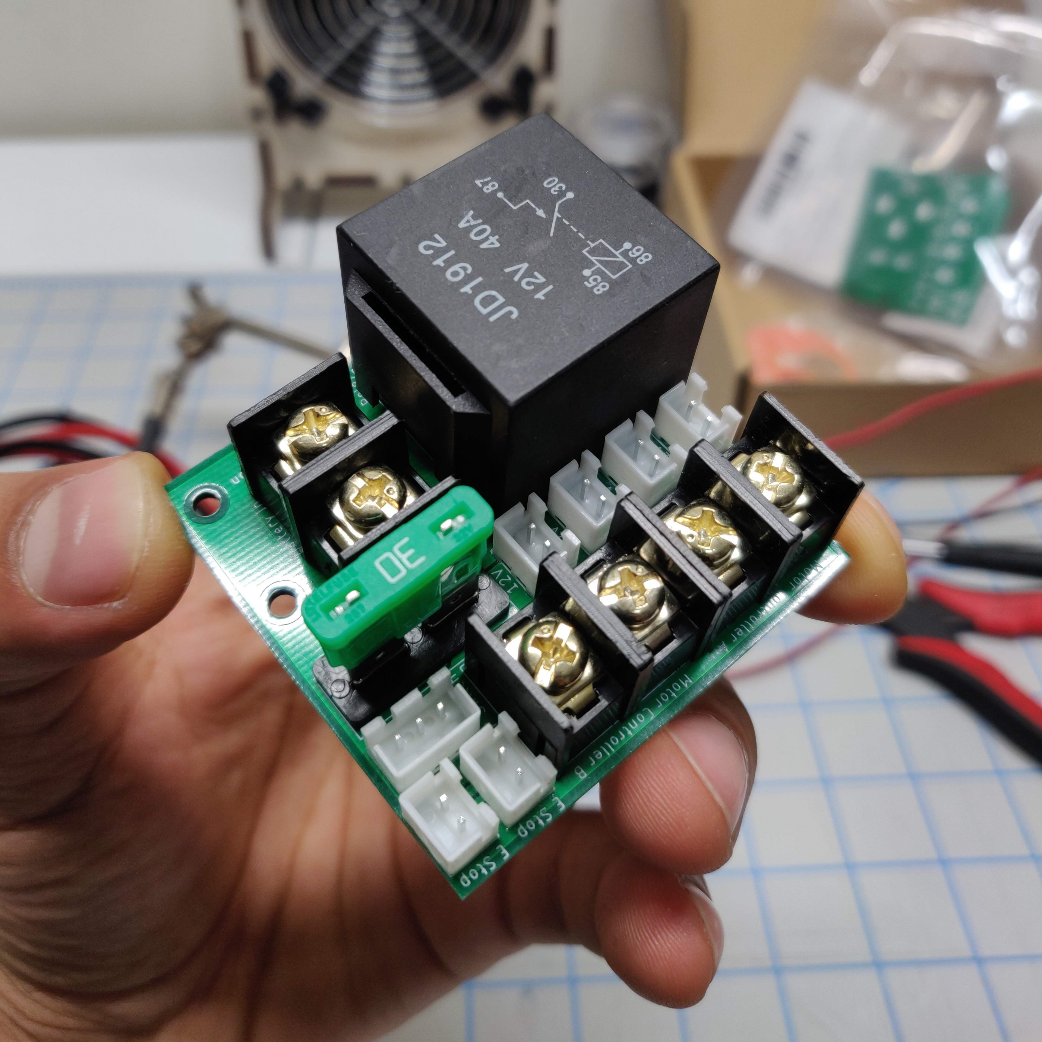
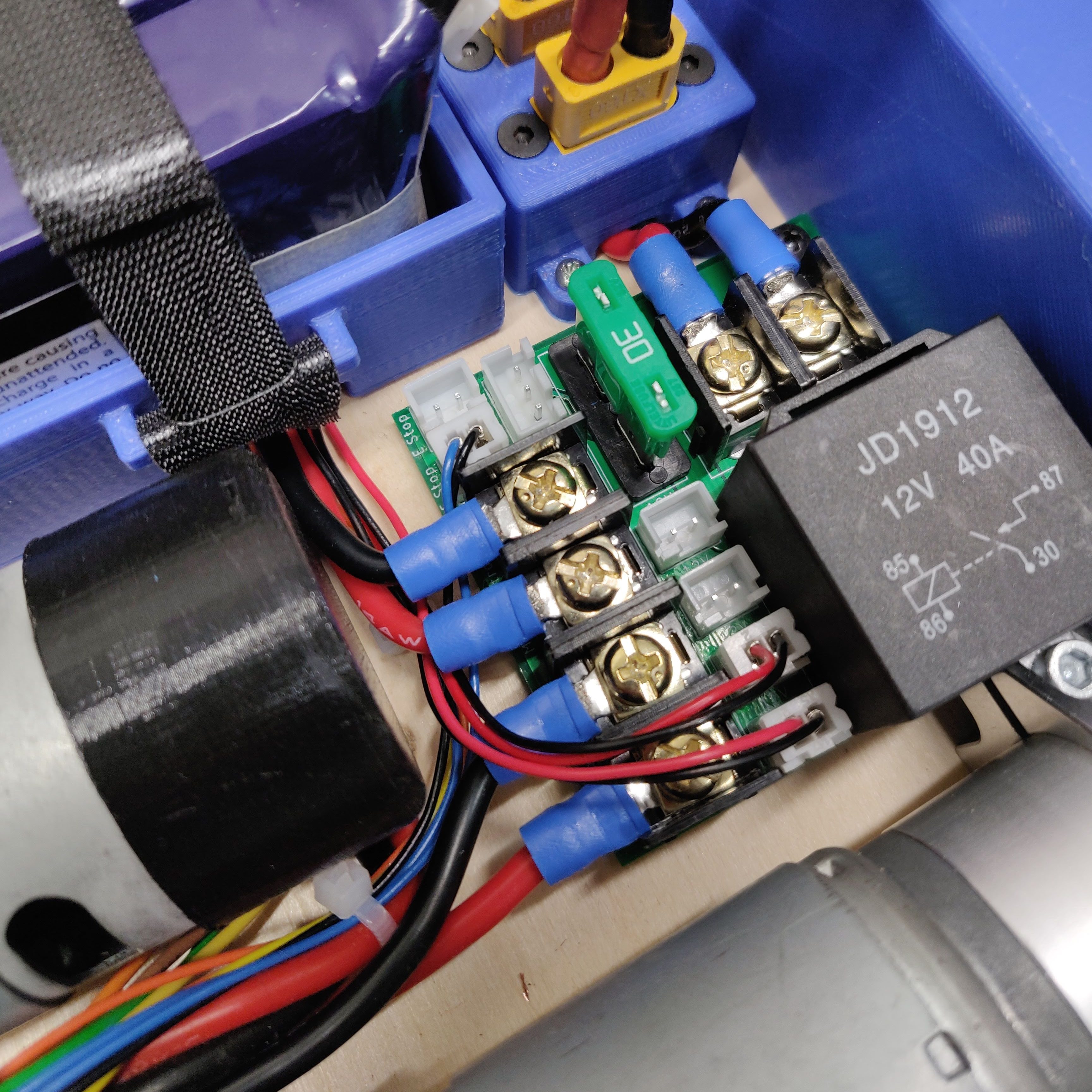
The PCB has a power relay that controls the main power to the rover using a much lower current signal from the power switch. I also added an automotive fuse and connections for an E-Stop.
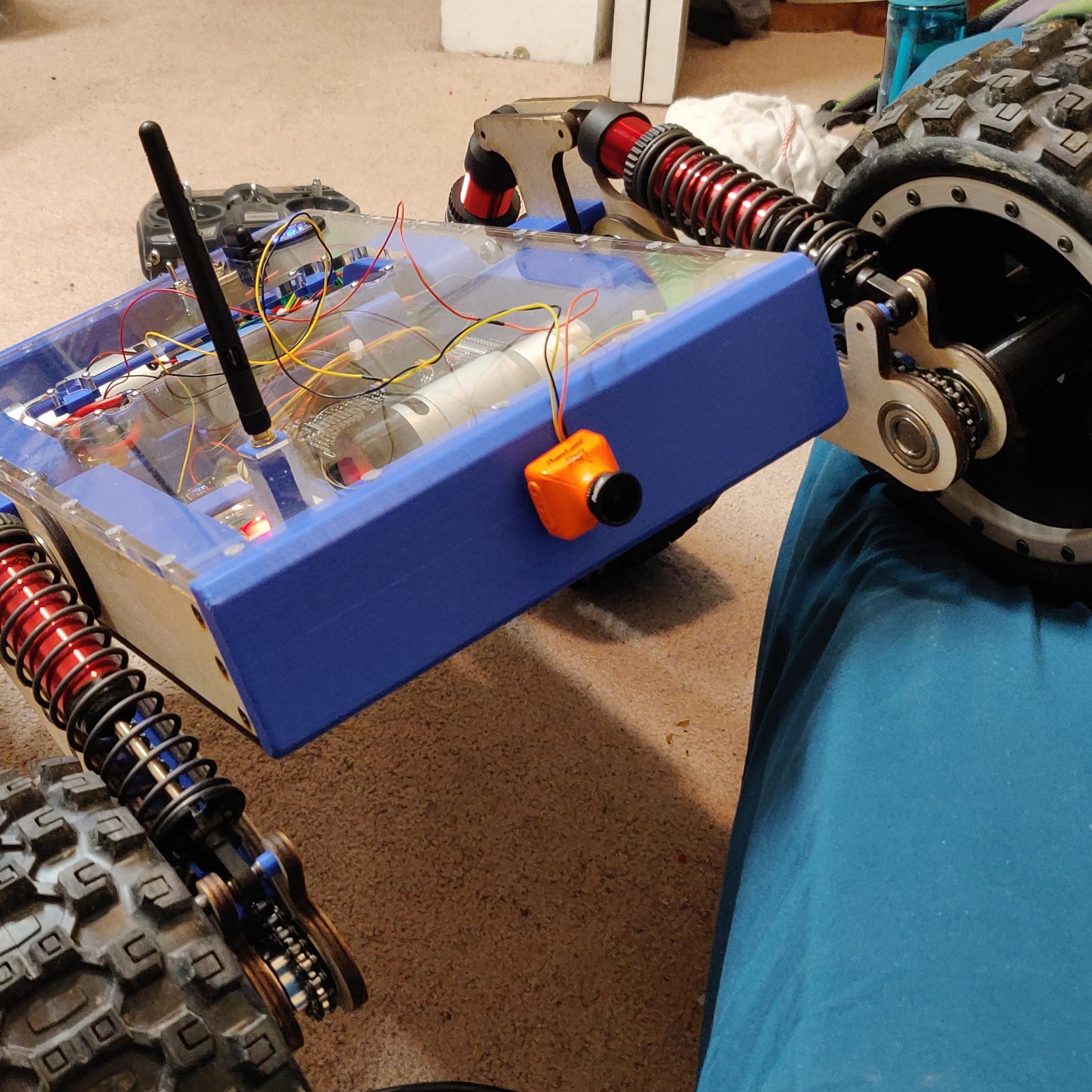
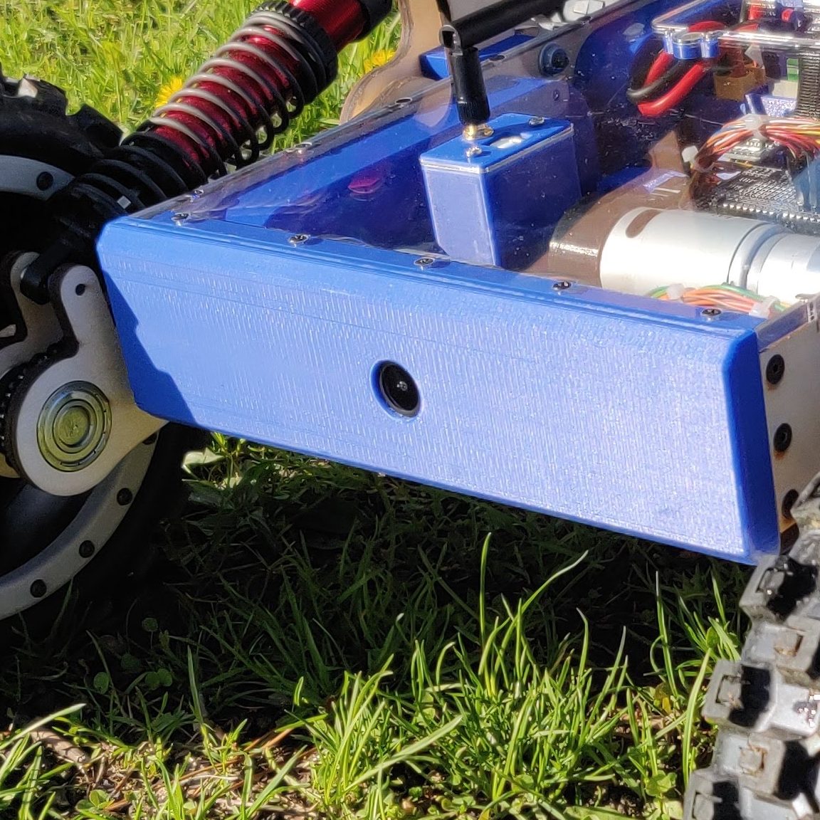
FPV Camera
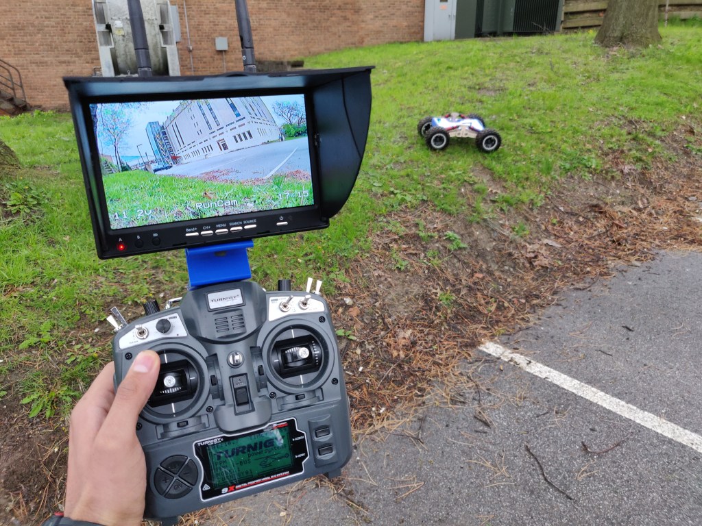
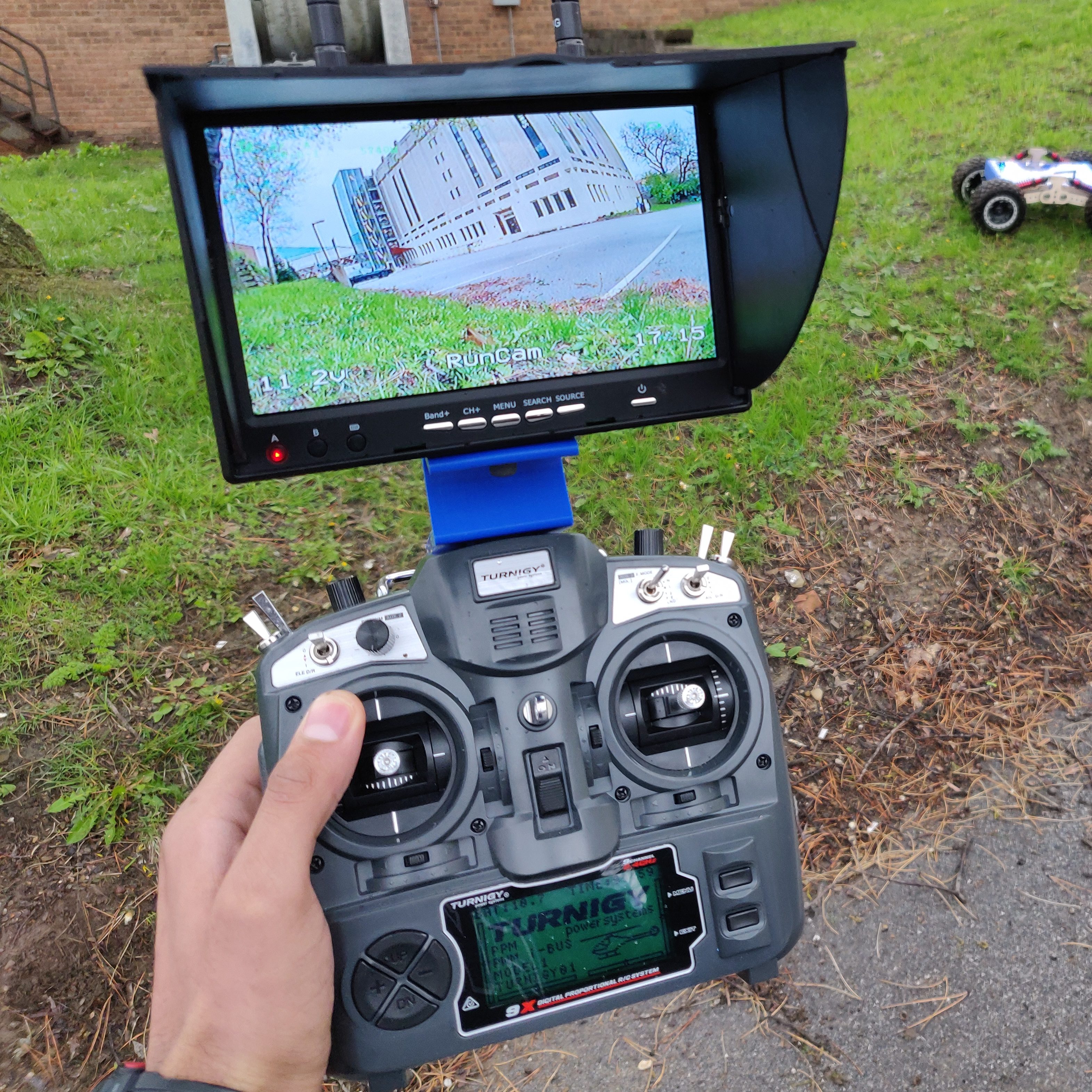
I wanted to be able to control the rover remotely and for that, I added an FPV camera, similar to the one used on drones. I tested out a good location for it and integrated it into the front end of the rover. I used a 2W video transmitter to transmit the video feed and a monitor with integrated receiver to view the feed. I mounted the monitor on my transmitter for easy viewing and control.
The range on the video feed wasn’t very good especially when driving without line of sight. If I were to do it again, I would have chosen a more robust video transmission system.
Top Cover
I made the top cover out of clear 1/4″ acrylic so that all the hard work inside is visible. I also added two LED strips for an added effect. The LEDs can also serve to indicate any fault such at low battery or over-temperature.
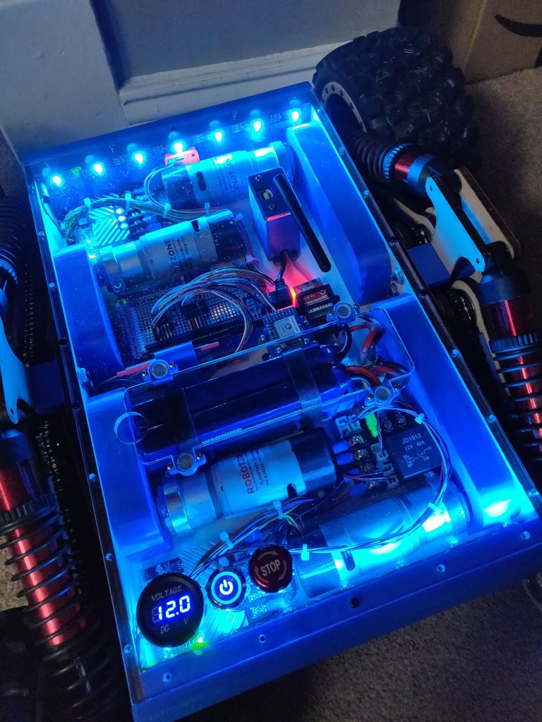
The top cover has a mini control panel on the bottom left including a battery voltmeter, power switch and E-Stop. I would have wanted a more comprehensive display to show more parameters but I couldn’t find a better solution.
Since the top cover is screwed in place, I incorporated a magnetic window to access the lithium polymer battery back. I didnt have integrated charging so I had to remove the pack to charge it. I did
Assembly
I spent a lot more time on the assembly this time. I even went as far as polishing the laser cut parts so that they look aesthetically pleasing and are more resistant to water. I redesigned a bunch of parts until they fit just right.
Testing
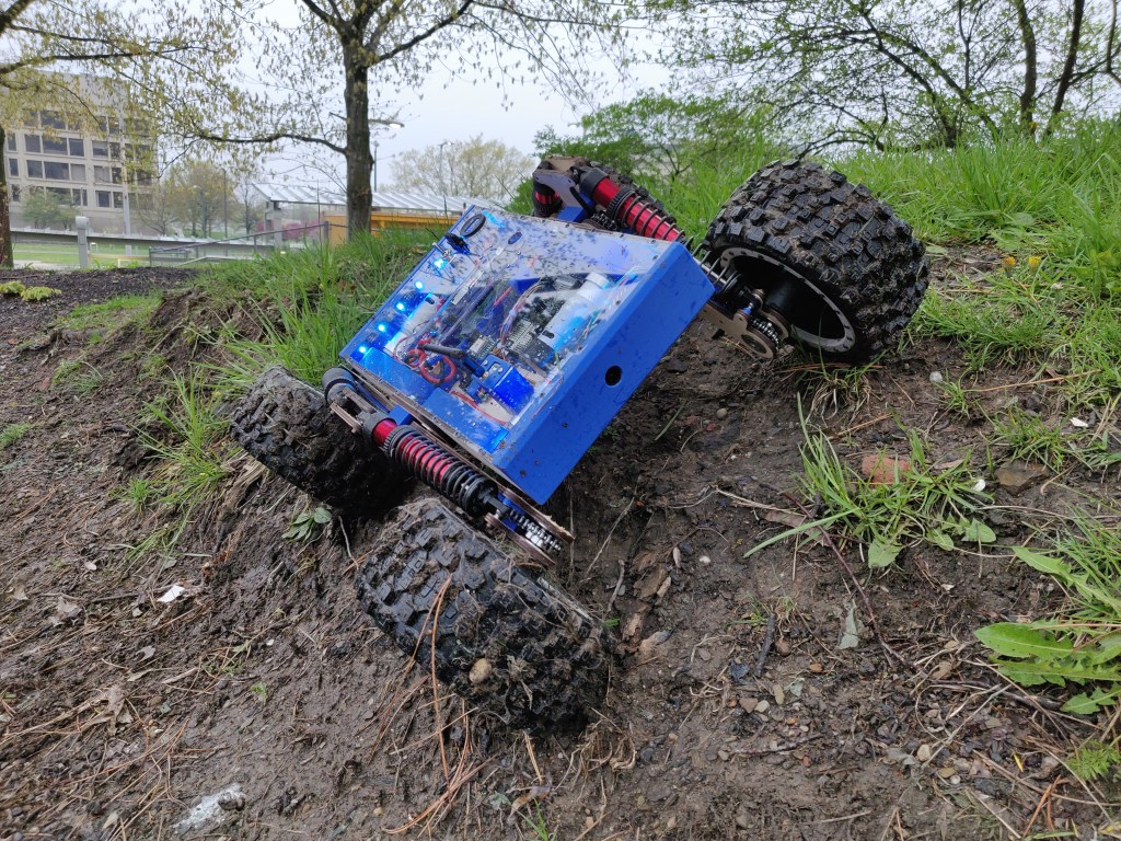
Testing the beautifully built rover was a bit painful but it was also a lot of fun and led to a lot of learnings. I didn’t go easy on the rover and took it through rough challenges including rough terrain, steps, falls, flips and rain.

After many hours of testing, some that led to broken bits, I started to realize the strengths and weaknesses of my design. As I expected, without adjustable suspension, its hard to position the rover and you just have to accept however the suspension naturally settles.
Lack of Adjustable Suspension
To allow for good ground clearance, you have to increase the ride height of the rover chassis. But that also increases the center of gravity and hinders its capability on steep inclines. Climbing stairs is also nearly impossible without adjustable suspension. So without adjustable suspension, the rover doesn’t offer too much off-roading superiority compared to a more simpler design.
In certain situations, the suspension would even hinder its ability to traverse and environment by getting caught or flexing too much. In a lot of cases, I wondered if having a simple rigid body design with minimal spacing between the wheels be better. Although that would similar to having a tank drive system just without the tank tread.
Too Heavy
The rover weights a lot. That in itself isn’t big problem but the more it weights, the more forces are exerted and more strong it needs to be. I think I could have saved a lot weight by using smaller bearings and lighter body panels. That would allow the rover to be more nibble and require less energy to move.
Limits of Prototyping Materials
I was pushing laser cut plywood and 3D printed part to their absolute limit and in a lot of cases, exceeding the limit. The revealed all the areas that would benefit from an upgrade in the materials and processes used for fabrication.
That being said, I was surprised at how good some of the parts held up to a lot of abuse. The main chassis didn’t show any significant damage even after number falls and flips.

Current Status
May 2023
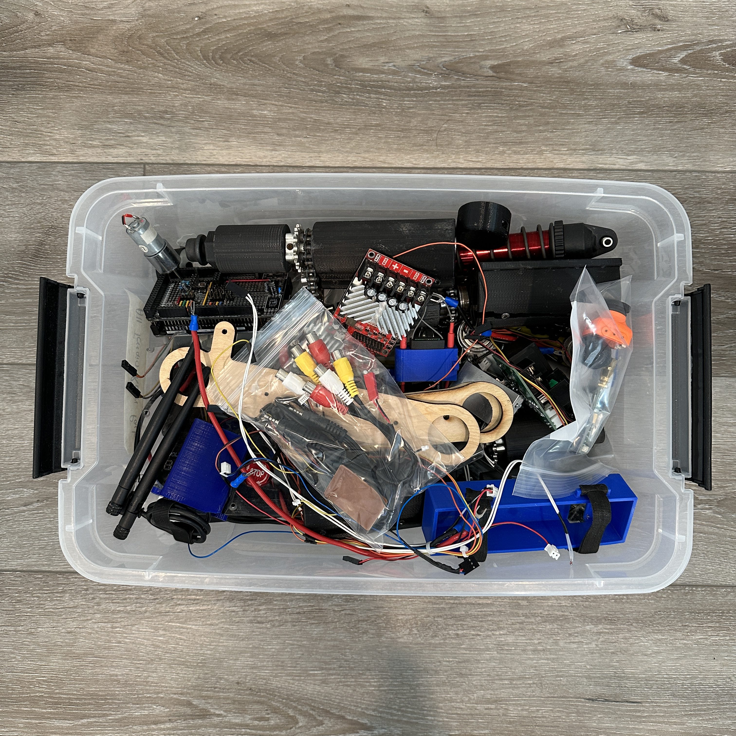
Lets talk about where this project stands at the time of writing. I built this project when I was in college at Case Western Reserve University. I bashed and trashed it until it was completely broken. I didn’t see a point in fixing it at the time because I wanted to work on the next prototype. But I didn’t have the time or money for the next prototype.
That was in 2019. Currently, it sits inside a bin, completely disassembled into parts. I don’t have access to a machine shop anymore so I don’t see a way I can work on the next prototype that will incorporate learnings from the second prototype.
Future Work
Just like many of my other projects, this project isn’t dead and I still want to work on it. My original goal to build a fully autonomous off-road robot seems to be very difficult to achieve but I think, I can definitely make the rover platform better and much more capable. Here are some of the things I would want to incorporate in the next prototype.
- Active suspension with position sensing.
- Aluminum suspension arms with lighter bearings
- Custom long range communication link for control, video and telemetry
- Custom control station to monitor the status of the rover
- Easier way to charge the rover
- Better battery and power monitoring
- More powerful on-board processor
- Control algorithms to assist in stability and movement
Conclusion
I hope you enjoyed reading about my All Terrain Rover project. I had a lot of fun working on it. Its unfortunate that I didn’t get to continue working on it but I am still hopeful that one of these days, with the right resources, I will pick back up on the project.
Acknowledgment
I would like to acknowledge Sears think[box] which is the university makerspace at Case Western Reserve University. Not only did I utilize tools and resources made available by think[box], the project was also funded by the think[box] Student Project Fund.
One response to “All Terrain Rover”
-
Very interesting and good work. Yep, plastic parts won’t last very long.
I really prefer a metal chassis, but I haven’t started building my project.
I’m searching now of whether I should install a suspension system or leave it without one.
But I prefer to install a suspension system even a simple one, at least to get a relatively stable camera recordings.

Leave a comment