Power Meter Data Logging

In this article, I will show you how I modified the cheap and popular panel power meters from Peacefair to read data into a microcontroller. You can get one and modify yourself using this guide and the provided example code, or you could buy a pre-modded version to get up and running in no time.
Github Repo: Link
Background
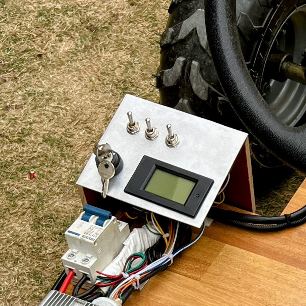
The idea for this came up when I installed a power meter in my electric go kart. I wanted to build a data logging system for it that can record the power stats along with some other metrics. One option was to add another power monitoring module that could record the current and voltage but I wasnt able to easily find one that can handle the voltage and current range of the go kart. And the added complexity didnt sit right with me since there was already a sensor isntalled.
I looked up if anyone has done a hack on these meters before where they tapped the data stream and were able to read it from a microcntroller. I only found one guide in which an AC power meters is hacked. The DC meters have a different architechture and the existing hack wouldnt work. So I decided to hack it myself, how hard could it be?
Power Meter Models
Here is a table of the power meter models that are most popular and what their capabilities are.
| Model | Type | Voltage | Current | Current Sense | Amazon Link |
|---|---|---|---|---|---|
| PZEM-031 (V4.0) | DC | 100V | 20A | Shunt resistor embedded inside meter | Link |
| PZEM-051 (V5.0) | DC | 100V | 100A | Big external metal shunt resistor | Link |
Note: I earn a small commission on Amazon purchases made through this post. But rest assured, my recommendations are not influenced by that at all. Any revenue will most likely go straight back into buying some more tools or supplies.
Reverse Engineering
The first step was to open one of these up and reverse engineer it to see where can we get the data from. The AC power meter hack I had seen before tapped into the data lines between the analog front end and the microcontroller. The DC power meter had the analog front end integrated into the microcontroller so that wouldn’t work.

I drew up a rough schematic for the power meter and started looking up the components. My next choice to tap into the data was going to be at the interface between the microcontroller and the display driver. I identified the display driver to be the TM1621B and found its datasheet. The hacking could commence.
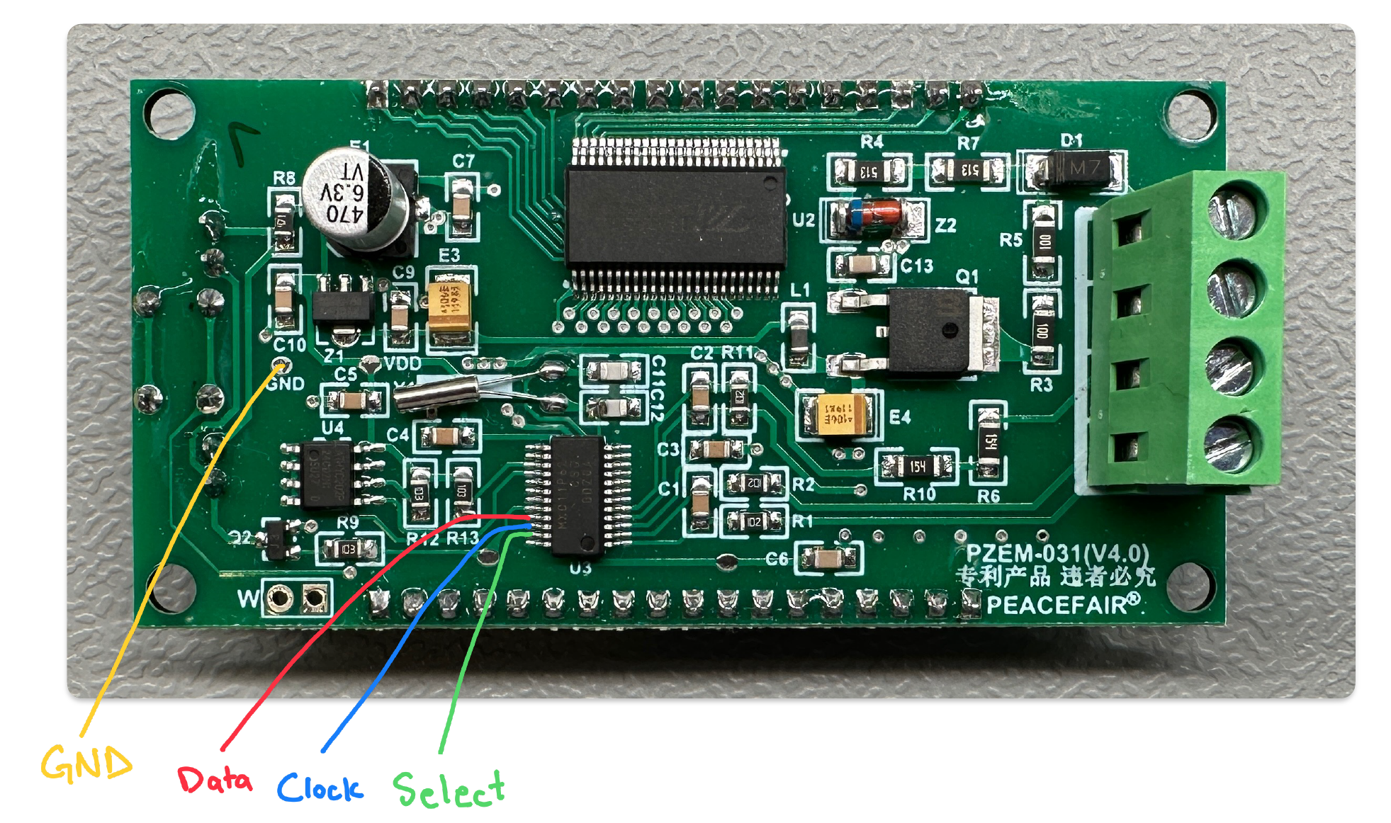
Soldering
Unfortunately, on the PZEM-031 (V4.0) that I was modifying, there were no easy locations to access the data signals, so I had to solder thin wires to the fine pitch microcontroller leads. I later learned that on the PZEM-051 (V5.0), there are easy to access test points that the wires can be soldered to.


Display Driver Data Packets
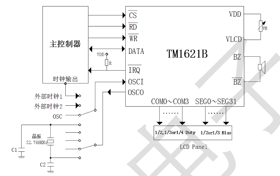
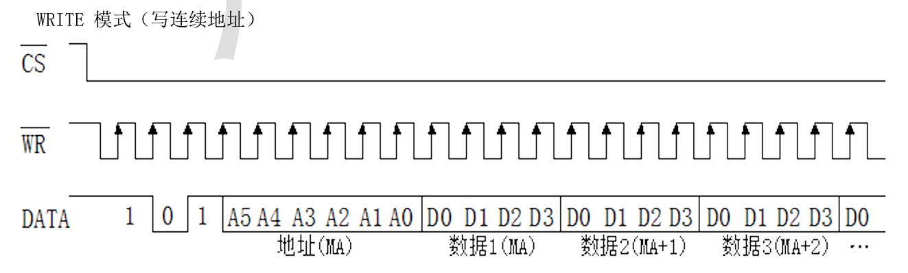
The connection between display driver and microcontroller consists of CS, RD, WR and Data lines. Looking at the datasheet, the communication protocol isnt exactly SPI, but its close enough that we could use SPI to read it, or so I thought.
The main difference is that in this protocol, data only flows on the data line and the read or write generate a clock signal based on either read or write. Whereas in SPI, the data flows on the MISO and MOSI lines and the clock signal is on the clock line. SPI allows for bidirectional data flow but this protocol doesn’t.
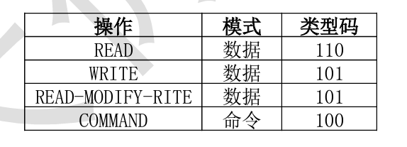
Looking at the CS line, I could tell that there were 16 packets of data, each packet 17 bits long. That made sense when looking at the datasheet since the first 3 bits were for the packet type, next 6 were for the memory address and the last 8 were two 4 bit numbers for to write to that address bit. These numbers would be the actual data that correspond to the digits being displayed.
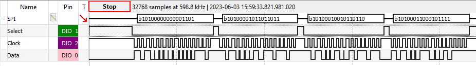
I tried to decode the data being sent at each address to the number being displayed but I couldnt determine exactly what each bit corresponded to. So I decided to switch over to reading this data from an Arduino instead.
I thought reading the data would be fairly trivial. The first mistake I made was to hook it up to an Arduino Mega which has a 5V logic level whereas the microcontroller in the power meter was 3.3V logic. I switched over to an ESP32 instead. The next challenge was to read 17 packets of data. Most SPI libraries are playing a role in the SPI transaction and cant just sniff the data. I was able to find a library to just read the data but it could only read in 8 bit chunks. I tried to get away with reading 8 bits but the last bit was important and without it, I would be able to discern between some numbers.
Hence, I switched over to bit banging the data using hardware interrupts. After some trial and error, I was able to read in all 17 bits of data reliably.
Packet Decoding
The next challenge was to decode the data values from the packets and correspond them to the digit being displayed on the screen. Instead of trying to figure out the mapping of each bit to the display, I instead combined the two values being written per packet into a single decimal number. I then used trial and error to determine the decimal number for each digit. I formed a lookup table and was able to decode the data.
I did run into some issues though:
- I had to drop the D0 bit for the data values for the first row and that was because they were encoding something other than the digit. Because I would get different values on the D0 bit for the same number at different locations. So I just dropped that bit by applying a 0x77 bitmask. After that, the look up table worked perfectly for every digit on the first row.
- For the second row, I needed the D0 bit of the data values as they encoded part of the digit, but D3 of the second data value had information about the decimal point. So I just shifted the data right by one bit to form my digit look up table and used the last bit to check if the decimal was active or not.
If this sounds complicated, that’s okay. I just spent a bunch of time to trial and error a solution so you don’t have to. Its actually more convoluted than it is complicated. I tested it with a variety of inputs and it gives the expected results.
I tested the decoding for the PZEM-031 and PZEM-051 but I could have missed some corner case where the decimal moves or something like that. If you find any issues, please file an issue on the github repo.
Code
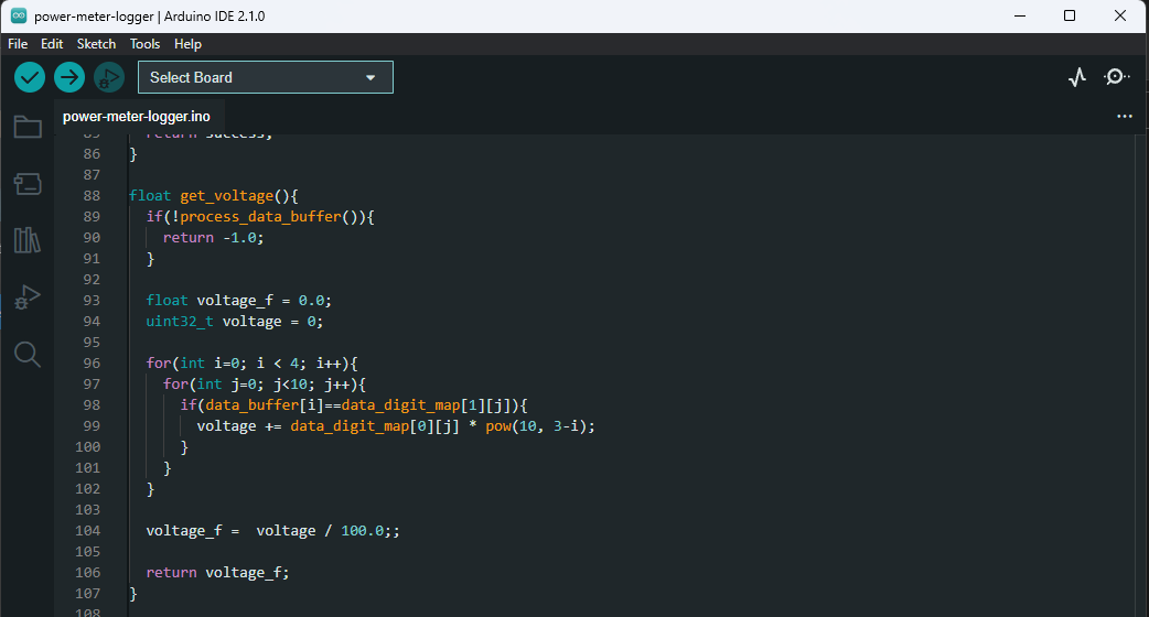
The code is written in Arduino and I tested it on the ESP32-WROOM dev board. It could be ported to other boards but they would need to have interrupt capability on the clock and select pin and have 3.3V logic level.
I wont go over the code in detail here but I have tried to add comments to make it as easy to understand as possible. Basically I am reading the data communication using interrupts, cleaning them up and decoding them to get the values I am interested in. The harder part of the code would be to understand the various bit operations I am doing since a lot of that was done by looking at the data on the logic analyzer.
Let me know if you have any questions about the code or anything else below.
Case Modification
I wanted to modify the existing case so that I can get the connections needed out and easily accessible. I designed a 3D printed back plate that holds a 4 pin female header.
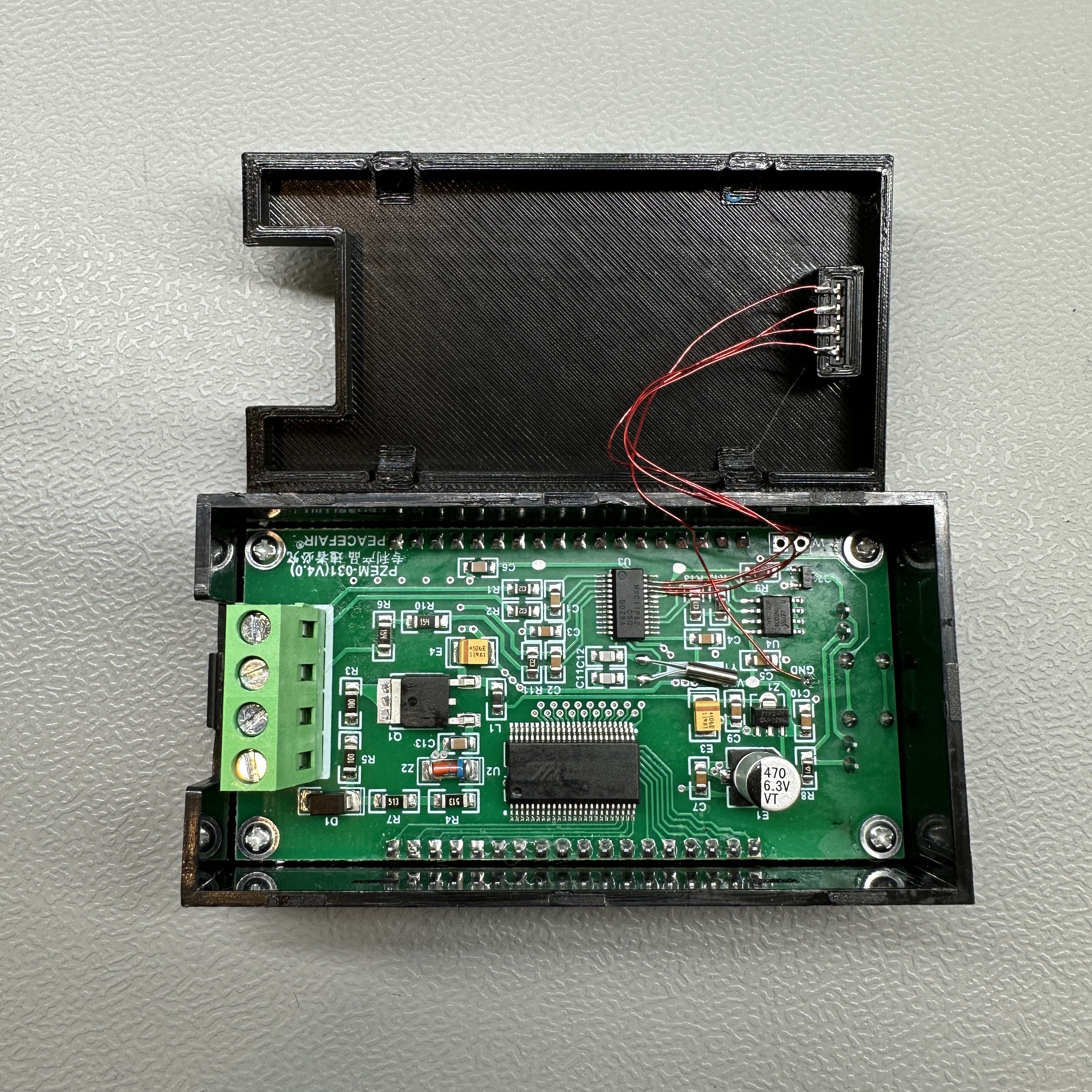
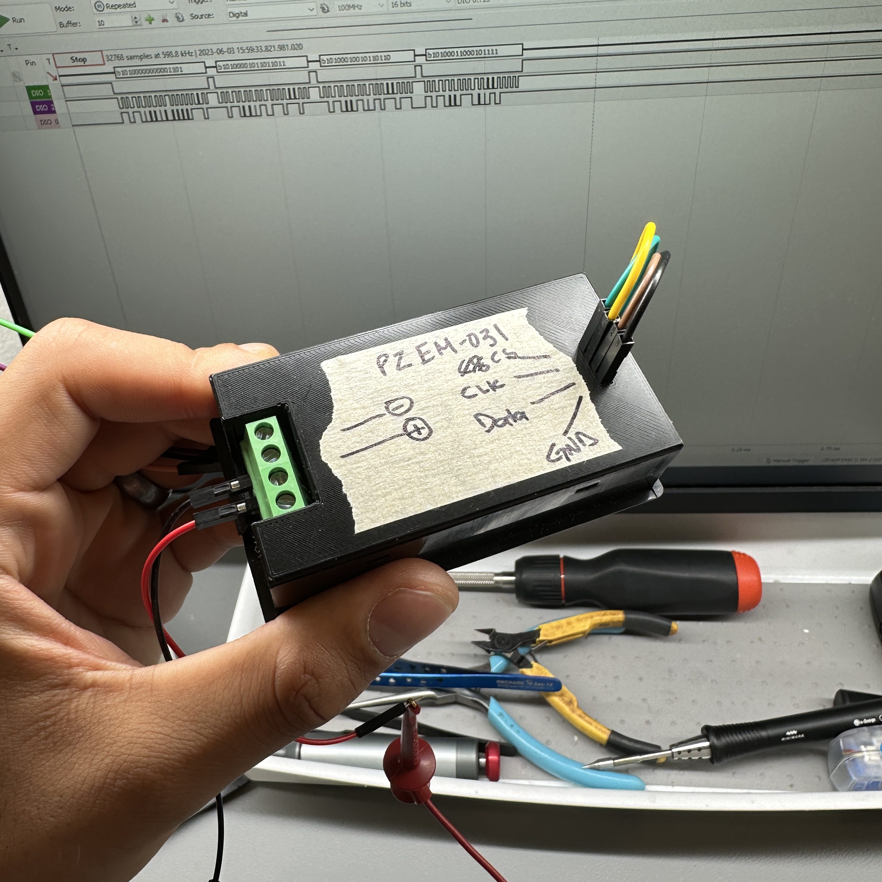
This worked fairly well although I might want to modify it to fit a locking connector like the JST-XH.
Conclusion
This was a fun little mini project and I was able to achieve the goal I set out for. You should be able to replicate the modification as well but if you are interested in getting pre-modified power meters, you can contact me. In any case, thank you for reading through and I hope you benefited from this post.
7 responses to “Power Meter Data Logging”
-
I accidentally changed the plus with minus of the middle two connectors. D1 was fried, but apparently something else is still broke. Which component do you think could be damaged?
-
Try disconnecting QNH2236 from VDD, and inject 3.3v to VDD instead.
If display shows numbers, its somethign on power side, betwen D1 and VDD. Basically builtin 3.3V regulator for display and MCU power.
if isolating/disconnecting QNH2236 from VDD and injecting +3.3V to VDD doesnt display any nubmers on display, its issue with MCU or Display itself, and at that point its not worth to repair. In that case i would try disconnecting display, and mesuring data pins. if you will recieve signal mentioned in this thread, display is death but you can use without display for purpus ementioned in this thread. otherwise microcontroller is dead.
-
-
I’m wondering why not just mount a Wemos d1 mini in the existing case and grab your data wirelessly? Does that sound viable?
-
Is it true that this current / voltage (PZEM-031) meter will, if connected in the recommended way, be permanently damaged if the battery were being charged instead of being discharged? Or will the meter continue to work and display / report a negative current during a charging event?
-
Test test, does this posting service work? I left a message days ago (probably 2025.05.14) and still have not see it.To the point…Thank you for this write up Badar.I’ve received a new PZEM-051 (V7.0) and it appears the BOM has been reduced! Only one chip is used to connect to the ADC shunt voltage and drive the LCD. The chip might be another version of the MXC11P62. There are plenty of what looks like unused pins on the MXC11P62. There are also some test points on the PCB. But only 2 are labeled similar to earlier designs pictured above. And those 2 test points buzz out to 2 LCD pins. So are assumed unlikely candidates for serial communications.It might be this new version offers no opportunity for tapping off the data. Have you seen this version yet?
-
Sorry for the late response. I have not seen the new version yet. I will check if I can reverse engineer that. If I do, I will post an update here.
-
-
Newer version drive LCD directly from processor.

Leave a comment