Ryobi Battery Repair Guide
Background
Some time ago, I had 3 of my new Ryobi batteries fail on me unexpectedly. That got me curious about what caused the failure. I went down a deep rabbit hole, buying dozens of broken batteries from eBay, reverse engineering the PCB and documenting my repair steps.
In this post, I will share everything I have learned including a detailed repair guide to help you recover your batteries. One of the failure modes that cause my own batteries to fail was very interesting so I made a video detailing that. Here, I will go into more detail about that and about the other, more obvious failure modes.
Links
GitHub: Link
Disclaimer
Working with lithium batteries can be dangerous if not handled properly. You are responsible for your own safety so please make sure you are following best practices.
Schematic
Here is the reverse engineered schematic for the PBP005 model battery. The schematic is like 95% complete and gives a lot of information to understand the topology and do some diagnosis.
Overall, the architecture is fairly common compared to other similar BMS circuits. The AFE chip is a mystery chip, either a clone or custom ASIC, with 3705T marking on it. I was able to sniff the I2C bus in attempts to read and decode the communication. But without any data sheet, I was not able to make much sense of it. I tried to use the TI BQ76920 data sheet but it doesn’t seem to follow that.
It also has an interesting circuit to detect if any load is present on the battery terminals. It can detect fairly high resistance loads and trigger the discharge MOSFET.
Failure Modes
Now I will go through all the failure modes that I discovered. Below is a tracker spreadsheet I put together as I was diagnosing and repairing each battery.
| Failure Mode | Prevalence | Symptom | Solution |
| Permanent Firmware Lockout | 65% | 1 Flash -> 4 Flash | Firmware dump -> clear lockout byte -> reprogramming |
| Cell Imbalance | 13% | Imbalanced cell bank voltage + 4 Flash | Re-balance manually using PSU and J1 reset |
| Soft Firmware Lockout | 7% | 4 Flash | J1 reset |
| Deep Discharge | 16% | Very low pack voltage (<5V) | – |
| Dead Cell Bank | 3% | Very low cell bank voltage (<1V/bank) | – |
| Bad Feedback Resistor | 3% | 4 Flash + incorrect voltage on AFE side of RF resistors | Replace RF resistor with equivalent part |
| Unresponsive Indicator Switch | 6% | TP32 >1V with button pressed | Remove R27 and replace R28 with 100 Ohm |
| D10 Diode Failure | 3% | No charging | Remove D10 |
Permanent Firmware Lockout
This is the most interesting failure mode. It is what affected my original batteries which started this whole thing. My best understanding is that in a scenario where the batteries are left sitting for a while, at some point the software thinks that the batteries are in some unsafe condition and triggers a permanent software lockout that prevents the battery from charging or discharging ever again. And the indicators flash 1 light on first click and then 4 lights on subsequent clicks.
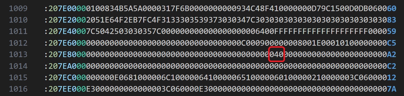
Initially when I tested some batteries with this issue, I thought it was maybe an under voltage lockout as some of the batteries did seems to be fully discharged. I manually charged them but was never able to recover them. I even balanced them down to 0.01 V yet they still seem to not recover. Jumping J1 to reset them didnt do anything. It was not until a lot of chip swaps and then finally jumping into reading the memory dump and cross flashing it, that I discovered that it was something to do with the software. A lot of trial and error led me to the exact byte on memory address 0x7E90 that when set to non zero, causes a permanent lockout and zeroing it, releases the lockout. I will share more about this in a bit.
Now my next question was what caused them to lockout. Some of the eBay packs I tested had cells that were fairly discharged or out of balance. So I suspected that those conditions could have caused it. But it was not until I got 5 almost new looking batteries, all around ~3V/cell with this issue, that I came to the conclusion that something is causing these to lockout under normal use or storage. I was able to recover all 5 of them by just zeroing the lockout bit and putting them straight on a regular Ryobi charger. These 5 were perfectly balanced as well and stayed balanced throughout some charge/discharge cycles.
Unfortunately, I didn’t record the exact status and steps I took on the initial batteries I had fail on me. But based on the information I have so far, my best guess is that these batteries go in some software state while in storage for a few months where the digital section pulls enough current to discharge them and at some voltage level along the way, it sets the software lockout. Because most of the batteries I got in this state, were fairly discharged.
The only case I have found to cause them to lockout this way is if one of the cell banks is ~0.15V less than the rest and the whole pack voltage is within a certain range, and then you put it on the charger, it seems to lockout. And that somewhat makes sense because under normal conditions, a pack should never have this level of imbalance.
So the true root cause of this failure mode may not be identifiable, especially without any visibility into the code. I will do some long term testing and see if I can replicate the failure mode. If I figure out something new, I will update it here. In the meantime, at least I know how we can fix it so if it does happen again, its a simple firmware re-flashing.
Firmware Flashing
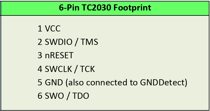
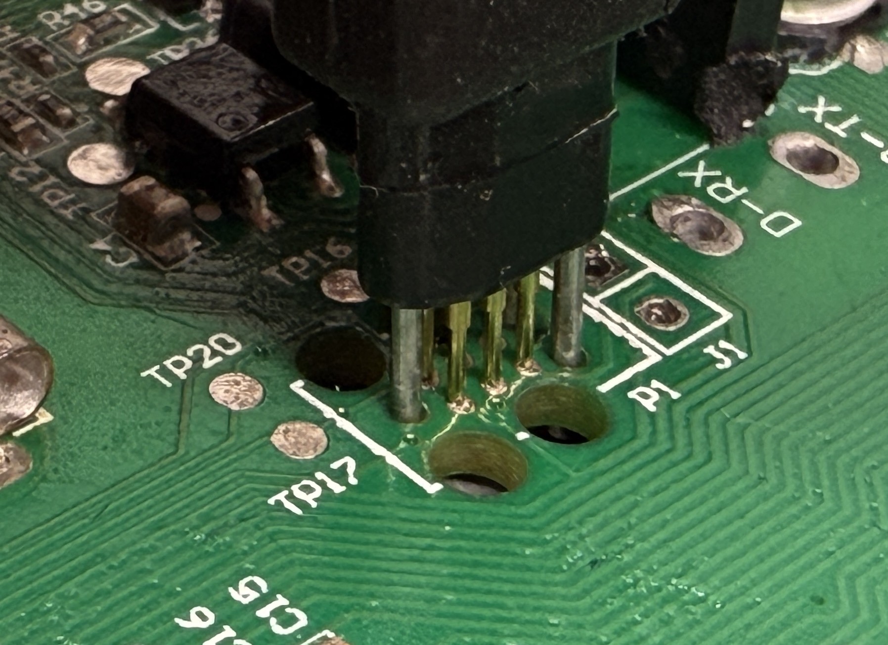
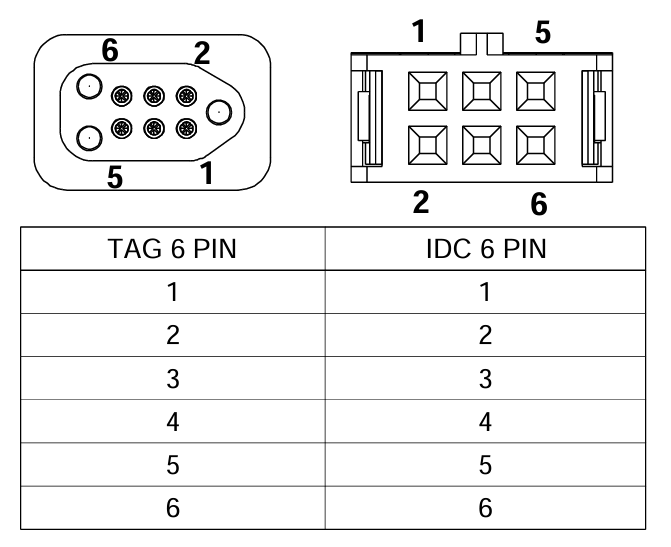
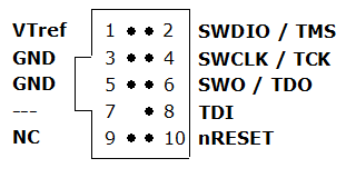
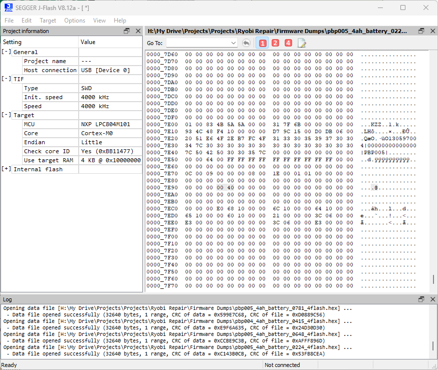
I will share a bit of information about how to dump the memory from the microcontroller, modify it and re-flash it. The microcontroller is the LPC804M101 from NXP. We have an onboard SWD Tag-Connect header that we can connect to using a Tag-Connect wire that you can get from here. I used a J-Link EDU Mini I had to connect to it that you can get from here. I wired the cable with the J-Link with some guidance from the data sheets of both products. Here are some diagrams I used to help me wire the two correctly.
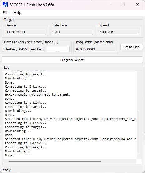
I then used SEGGER J-Flash to read the memory of the microcontroller and save it as a hex file. I mainly used VSCode with the HexEditor plugin to analyze and compare the firmware dumps. I can then modify the hex file to clear the lockout byte on memory address 0x7E90 and then use SEGGER J-Flash Lite to program the microcontroller.
Cell Imbalance
Some packs had some cell banks out of balance and indicated the 4 flash error on the LEDs. This could be due to a few things, it could be just some cell banks having slightly higher internal resistance than the rest, and under heavy load, getting out of balance. What my testing revealed is that the cell balancing on these batteries is very slow and only happens if the cells are within a certain range. The 500 Ohm resistor limit maximum balance current to ~8mA. It is also dependent on total pack voltage and level of imbalance so very hard to determine the exact logic.
To fix this, I manually balanced the cell banks using a power supply at a constant current of 0.5A. And to recover, I performed the J1 reset which goes as follows.
Click the status button -> short J1 jumper -> click the status button again -> LED 2 and 4 light up-> open J1 jumper -> done.
It is possible that the pack goes out of balance again if the affected cell banks have higher resistance. Heavier loads will make it worse. It is also possible that some fault on the PCB is draining some cell banks more than others. And it could also be due to higher internal self discharge due to cell damage. These could make this problem keep coming back and the pack never fully going back to its full capacity. I have seen cases of all of these and will continue to monitor some of these packs to see how they fare over time.
Soft Firmware Lockout
The pack enters this case if at some point it senses a cell imbalance. I saw a few cases of these where the pack actually was balanced but it triggered the software fault and flashed the 4 LEDs. My best guess is that either it sensed incorrectly at some point or was imbalanced at some point but overtime balanced itself.
Regardless, the fix is fairly simple and there are many Reddit threads about this. It is the J1 jumper trick I mentioned above. The reason I bucket this into a separate failure mode is because in this case, there is not noticeable cell imbalance. And I am also not certain that there weren’t some other conditions that cause it to get into the fault state. But resetting the fault case is relatively simple.
Deep Discharge
*** image measuring total pack voltage ~ 2.5V ***
In this case, all 5 cell banks will be less than 1V. What I have found is that in some cases, each cell is completely flat at 0V. That likely is due to the board having some sort of a load to ground that drained the cells completely. This can be due to water damage as I did notice a few of the water damaged boards have totally dead cells.
In other cases, each cell is around 0.5V with a pack voltage of 2.5V. My best guess is that the digital subsystem went in some state where it pulled power continuously and kept doing that until the load on the 3.3V didn’t go away due to low voltage.
In either of these cases, I would not recommend recovering these cells as deeply discharged cells will most likely have some permanent damage that can make them unsafe to use, especially for high draw applications.
That being said, I was able to recover the packs with 0.5V cells using a very slow trickle charge to bring them up to 18V and then charging them as normal. I put a few cycles on them and tested them using a internal resistance meter. I did not notice anything wrong other than slightly reduced capacity. As I would trickle charge them up, the 4 LEDs would flash continuously until I desoldered the Power jumper to power cycle the microcontroller. My guess is that the microcontroller did not like seeing the pack at such a low voltage and was just upset about that. But after the power cycle and a subsequent J1 reset, it was happy and working as expected.
Once again, I would not recommend this and even for my own use, I will likely only use these packs for very light loads. One of the packs I tried to revive started heating up when charging and measured to have higher internal resistance. I safely discharged that pack, not to be used again.
Dead Cell Banks
*** image measuring dead cells on multimeter ***
This case is similar to the deep discharge but only for some cells banks where they are totally dead at 0 V. If that is the case, then the pack is toast and there is not good fix for it since even if you can recover the deeply discharged cells, they will certainly not retain their balance with the rest of the pack and keep going out of balance. Your best bet is to remove the good cells and reuse them for other projects.
The question is why would this happen. My best guess is that some fault on the BMS caused a constant high load on some cell banks that drained them completely. This could be due to a component failure or water damage. But I don’t have a full analysis on this failure mode.
Bad Feedback Resistor
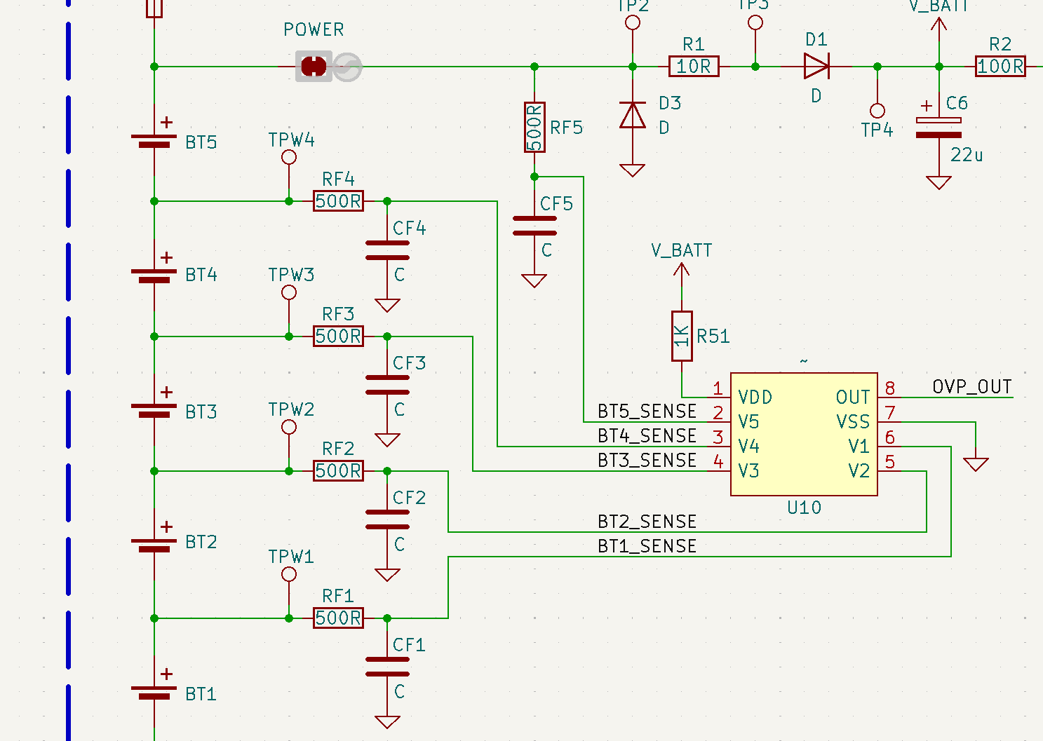
Another related failure mode I have seen is failed RFx feedback resistor which was not feeding the sense voltage to the AFE chip. I only saw one case of this and the board did have some water damage. So it is likely related to that. But I was able to replace the damaged resistor, J1 reset the pack and it started working as expected.
Unresponsive Indicator Switch
This is another failure mode that I was able to fix yet don’t have a full understanding of what would cause this. In this, the indicator switch becomes unresponsive. The tool will discharge fine if it has some charge but it wont charge.
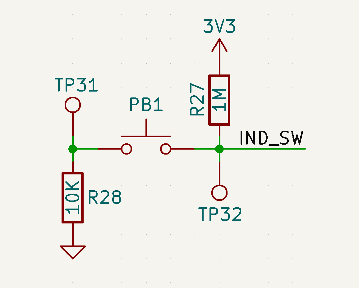
I was able to determine that the pull up resistance between TP32 and 3.3 V rail is fairly low, ~1k. Hence pressing the button didn’t fully bring TP32 to GND, which triggered the GPIO. To fix it, I removed R27 and replaced R28 with a lower resistance ~100 Ohm. And this solved the problem.
My best guess is that some voltage spike on the 3.3V rail injected into the microcontroller GPIO line and cause damage, leading to a lower internal pull up resistance. Maybe, putting a zener diode on this to limit the voltage may help. I could also see it being an ESD induced damage although I don’t understand ESD mechanisms enough to comment on that.
D10 Failure
Unsolved Failure Modes
There were a few failure modes I was not able to figure out a fix for. A couple of the boards had a charging problem where they would not be detected by the charger. I tried to dig into the T1 circuitry as that is most likely where the issue was located. I was able to short TPxx to ground to force it into charge mode and prove that the issue was in the T1 logic circuit, but never was able to fix the fault in the circuit. It didn’t help that I didn’t have the exact part numbers for some of the transistors and they also were powered so any wrong move would send V_BATT where it is not supposed to go and cause other damage to the BMS.
Conclusion
I hope this guide can help you recover some of your Ryobi batteries that are healthy yet rendered useless by the BMS. If some or all of your cells are bad, then it makes sense that you safely recycle the pack, but if the cells are healthy and just the BMS is holding it back, then I would recommend using this guide to recover your pack.
I think there is a bigger question here and that is if this new approach with so many firmware based check and locks is better for safety and longevity or not. Because on one hand, I do get that you want to ensure safety while using the batteries and avoid any catastrophic failures in the field. But on the other hand, you also have designed something that seems to have a high false trigger rate, rendering perfectly usable packs to become e-waste.
The cynic in me would think that this was a deliberate decision by Ryobi to ensure that they can sell more packs. But I don’t know if I buy that since Ryobi batteries have a 3 year warranty. My original packs were less than a year old and I was able to get all of them replaced under warranty. Interestingly, one of the replacement packs also failed similarly.
But my best guess is that Ryobi had good intentions and wanted to ensure user safety but they didn’t test the batteries thoroughly enough to ensure that false triggers don’t occur. And since they implemented a lockout feature that doesn’t self reset, the pack would become useless if the protections are triggered incorrectly. I hope they have already implemented a fix for this and improved their firmware to eliminate the false triggers.
43 responses to “Ryobi Battery Repair Guide”
-
So valuable article, thank you so much for all your effort!
-
soooo….. You’ve done the work, finish it with a solution and either sell it to Ryobi or give it to the world. Logic dictates that Ryobi doesn’t want this to be available so maybe they’ll give you a bucket of money to keep it quiet.
-
Really informative and interesting, but wouldn’t it just be easier to buy a new battery 😀
-
Man the world would be so boring if everyone just did what was easy.
-
-
-
can you check into the 80v battery’s? We are having same bms lockouts when batteries are fine
-
This is gold. Now I want to replicate your work. Good job.
-
nope lazy people couldn’t be bothered to fix something throw it away days are here to stay .good work man you are one of the true battle workers.and worthy of the highest praise
-
not all people are electrical engineers. It was all Chinese or you just wanna show off your education
-
thanks for all the efforts, very helpfull
-
I am a retired from work and now call myself a tinkerer with degrees and experience in electronics. Also I own approximately 20 18 V Ryobi Batteries. I anticipate these batteries will have problems in due time.
This information provided you by will be very valuable, so I will save your site including the videos. THANK YOU very much.
-
what does the T1 and T2 circuits do? It isn’t clear in the schematic.
-
Mine just failed last sunday.
The cells are not unbalanced and the NTC is 10K at room temperature.I discovered this post after starting the reverse engeneering of mine BMS.
I managed to find the AFE chip marking and while attempting to find
the datasheet I instead stump on this article.My battery is a RB18L20 and it doesnt have the LEDs and the MCU is a ATTINY 88.
My board is full of what seems to be opams or mosfet drivers.I wasnt expecting this much discrete parts.
I was trying to figure out what whas the 3.3V onboard regulator
and looks like it was the mystery chip all along.Once I figure out how the two “mystery contacts” (center and the base pins)
do in the battery I’ll probably design a new BMS PCB.It is a shame. The drill In my case is 1.5Y old.
Warranty cover the battery only for the first year.This is my first battery powered tool and the first impression is very bad.
If you’re interested I can share the results/pictures of my board!
-
Ryobi batteries have a 3 year warranty. Even if you do not have your receipt or didn’t register your tool, Ryobi can at least go off of the date it was manufactured, and if it is less than 3 years on the battery–they should replace it under warranty. Call them and give them the serial number so they can check. Either way, go to their site and register the tool and battery, then call them and ask for help.
-
Did you figure this out, I connected up a RB18L50 to new cells after 1 of the 5 parrallel cells were dead shorted.
Connected jumper GND and RST, which is also connected to the pads below labelled PAD.
Lights flash indicate 20 times.
-
Did you purchase it new? According to the Ryobi Site all 18v batteries are 3 Year Warrantied.
-
-
This is great work, and I congratulate you on your success! While I do not have any Ryobi battery pack tools (I do own a Ryobi corded drill that I am happy with), I have been looking into restarting laptop batteries as they are also locked up by the chips.
If you are feeling bored, perhaps you can branch out into that area too? I’d love to see any solution you may come up with for laptops! -
Great write up and work!
i have a couple of batteries that suspiciously stopped so i will gladly go through this with those batteries
-
Please please please fix the E5 errors on the $900+ 80V RYOBI batteries! I will send you my non-working batteries and find a working one for you if you can fix my giant paperweight!!!
-
I had two of these batteries fail so I desoldered the bms and piggybacked the pack onto an older ryobi battery, using 2 thin 10amp soldering bands for solar panels. It works fine but I am not using it for high output, only led lights and radio. I obviously welcome your post and the youtube video, but due to legal environment it is very unlikely that ryobi would even admit this fault. Moreover, your findings have not been replicated by a third party lab or researcher as of yet. Usually with this kind of control software there is some hardware based easter egg that lets you reset the lockout, like, for example, (but for emphasis, this is not the case) charging the battery and pushing the charge status button, the so I would like you to focus on finding that easter egg because that would benefit the most people who do not have the resources to purchase an an arm debugger and probe.
-
The same thing happens to the 40 volt batteries, but those batteries are twice as much as the 18 volts. You could literally start a business fixing these things. So the only way to fix it is to replace the microcontroller?
thank thank you!
-
With a firmware lockout, you have to clear that one byte. Only way to do that is with JTAG. You don’t need or want to replace the microcontroller.
-
-
Anyone know if this set of techniques will work for the 40v batteries?
-
I’m trying to get it to work but I don’t know what microcontroller is used on the 40 volt battery. If anyone can tell me that would be helpful.
-
-
Awesome guide! I will use this to help myself, family, and friends acquire cheaper batteries by buying dead ones in bulk. much better than becoming e-waste if it can be avoided. It’s nice having a few extra batteries around with vacuums, fans, power adapters that my family regularly uses now because the batteries make it so convenient.
Can you make a step-by-step guide on how to reprogram the battery?
-
I tried this already, I think the bug he came across was much more recently . About a year ago these started showing up in mass. However 2-3 years ago I attempted to do similar with the 40V. Out of 200-300 batteries purchased I notice 80% had been messed with to the extent it was more effort than it was worth as New quality individual cells could be purchased. I would only advise it on unopened and untampered with batteries, which in my conclusion disappear as soon as one of these you tube videos come out.
-
Yes please. I bought the J-link and Connector specified in this guide. I think I can do it, but a step by step would help tremendously.
-
-
Very nice work, helps alot for new one. Just bougt 26 pc roybi 4 ah battery with zero volt (0,2v) most are charger slowly up to 16 volt a 0.2 amp. first stess test was really good. got 4 ah and inner resistance a 13 ohm.
-
I had the four-flashing issue on my PBP005. I opened up the pack and saw one cell pair at 3.6v while the rest were at 4.1. I balanced manually and tried the J1 reset but it didn’t do anything. I eventually desoldered and resoldered the “power” solder jumper to cut the BMS power supply, and that worked.
YMMV, risk of course.
-
Tag-Connect has a cable that can directly connect to J-Link EDU mini ( TC2030-CTX-NL ).
-
My 40v battery failed within the first year after I purchased it, with only 2-3 charge cycles. Maddening.
Bought another. Worked for one full charge cycle and failed again in the exact same way (flashing 4 LEDs). Unfortunately I didn’t keep the receipts for any, so I can’t do a warranty claim. Will try these. Thanks!
-
This is a great article and you must have spent a great deal of time researching it.
I too am puzzled by the mystery contacts on top of the battery management board and on the contact pillar. Did you find out what these were and how they functioned? I presume that they are to tell the Ryobi charger that a genuine battery is being recharged or that is connected to a tool but what do they actually do?
-
One problem that I haven’t seen addressed is when a battery is fully charged (no blinking lights) and works in the tool, but cuts out after a few minutes of use – for me this is a blower. Turn the tool off and wait a couple of seconds, the tool now works again. Then, after a minute or so cuts off again. The work time gets shorter and shorter. Let the tool sit for a while, start again, and the symptoms repeat. Is there a fix for this?
-
Any idea if this might happen with third-party batteries too? Would I actually be better off buying third-party batteries?
-
Any idea if this might happen with third-party batteries too? Would I actually be better off buying third-party batteries?
-
Hello! Great work. Thank you for sharing useful information with other craftsmen!
I have a question. Have you ever come across a battery with a “P108 eve20p2” BMS board? If so, could you share the working firmware? -
Nice to see there are others likw myself wanting answers. Keep up the good work.
-
I am having the same problelm. All four leds flashing. Will not charge. I opened the pack and the batteries read full voltage. No imbalance, no low voltage. I did the J1 reset and got it where just 1 led comes on when pushing the test button; Still no charging. I will keep trying but at least there seems to be some progress. Hate to throw it away. It reads full voltage.
-
I had 4/10 cells at a lower voltage than the others. balanced them and still can’t get rid of the four flashing lights.
-
I press the battery button and nothing lights up. I put in the charger and it briefly flashes red and then goes solid green (indicating it is fully charged?). Is there a solution? I’ve seen videos where people try to connect a good battery to the “bad” battery (without taking apart), but will that work? Or do I need to take apart and try to charge the batteries with the casing off?
-
In one of my battery packs, the cells were way out of balance. I balanced them, but the status lights would blink 4 times. I tried yhe J1 short/jumper trick and it worked! So thanks! I have another battery with the same issue, so I will try that on this one too…
-
Incredible work! Many thanks!
Impecable trabajo, me fue de mucha ayuda, gracias!
Deberia estar prohibido este tipo de practicas por empresas como Ryobi, el bloqueo por software no hace más segura una batería solo hace que sea inservible más rápido.
-
Would a St-link work to reprogram the battery?
-
Thank you very much for providing details on how to repair these batteries.
My battery was a 2A 18v Ryobi model PBP06, usual problem all four leds flashing and unable to charge.
Using the Segger J-Link debugger (v8) to communicate with the battery and inspecting block 07E90, unlike your result of “040”, mine had a value of “242”? I changed this value to “000” flashed the new code but no change?
I did have work 18v PBP06 battery, so I dismantled this and took a copy of the code. At 07E80 the values were “000”, but I also noticed that there were many other changes in this area of code.
I flashed this known working version of the code onto the faulty battery and it worked!
Some strange things still exist,
- When connecting via the debugger to the known good battery it connects immediately, the faulty battery will not connect unless you first press the yellow button on the battery?
- When writing the code to the battery, this needs to be done twice or it will fail a verification test?
- When disconnecting the debugger from the battery I always use the “Disconnect” command to reset the battery CPU, you need to do this this twice then all leds on the battery will extinguish and the battery will function.
Hope this helps other people with repairing their batteries.

Leave a comment