Iridium – Autonomous Mobile Robot
2020 – 2026

The Iridium robot is a 4wd differential steering mobile autonomous robot running ROS2 (robot operating system) and designed to be a learning exercise in building a mobile robot and getting it to navigate autonomously in an indoor environment.
In this article, I will walk through the hardware and software architecture of the robot. The software is still in development so I will leave the complete autonomy stack for a later article and just focus on the basic interfaces I built to get everything connected and talking to each other.
Background
I started this project in college (circa 2020) when I was taking robotics perception and navigation classes in undergrad and wanted a platform of my own that had high quality sensors and compute to be able run more advanced algorithms like visual slam, computer vision, ML model etc. I had built some robots before but none with the quality of sensors or compute that I wanted.
I worked on it for a year, was not able to get past some basic ROS setup and then got busy with my job. Recently (2026), I had a renewed interest so I picked back up on it again, made some changes to the hardware and have started developing the autonomy stack. I know a lot more now than I did back then and I also have Claude Code assistance to help me with the software side of thing.
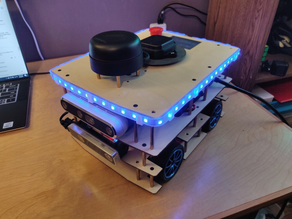
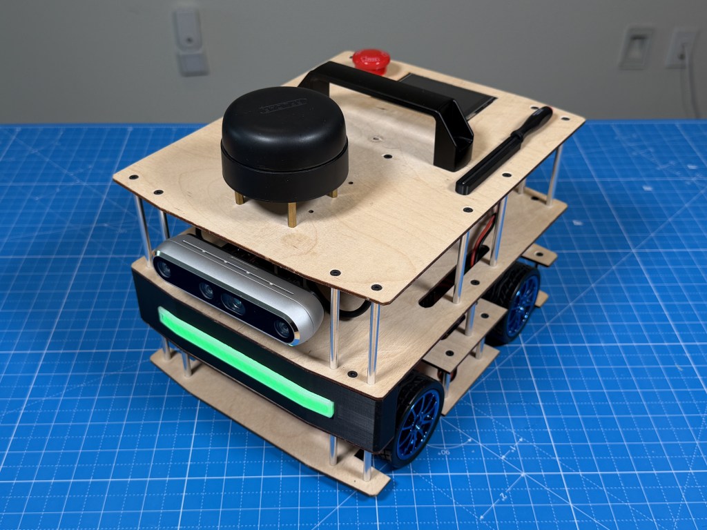
This is how the robot looked when I was done building it in 2020. LED strip was my idea to do a cool distance visualization but I ended up getting rid of it. I have also made other changes that I will talk about later.
Architecture
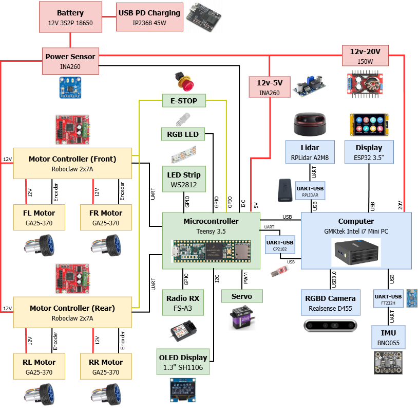
Here is the architecture diagram of the whole robot that shows how all the components are connected to each other.
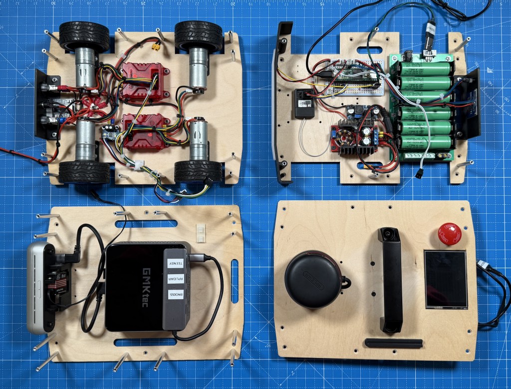
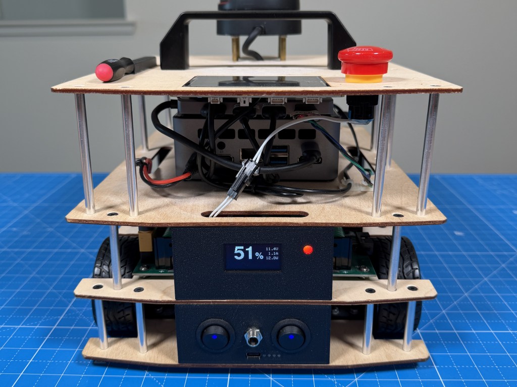
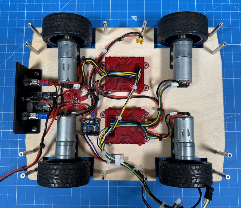
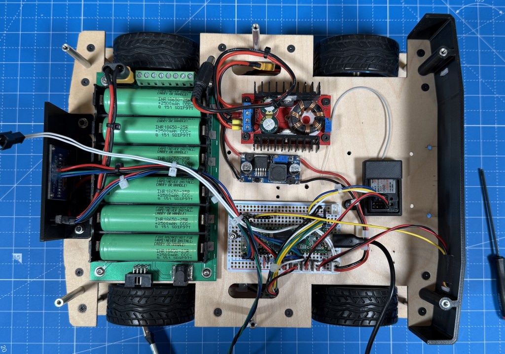
The robot is physically divided into stacks as well and those represent the different blocks. The bottom layer is drive. It has 4 12V geared brushed DC motors with encoders. They are driven by 2 2x7A Roboclaw motor controllers. I have the power switches controlling main power and motor power as well as the external power input, USB-C charging IC and a voltage/current monitor.
On the next stack is the lower level control with the center piece being the Teensy 3.5 microcontroller. Its main job is to interface between the computer and lower level peripherals. So it has connection to the motor controllers over UART, power sensor over I2C, OLED status display over I2C, RGB status LED, status LED strip, camera servo, e-stop and radio receiver. It connects to the robot computer over UART using a CP2102 converter for data but also has USB connected for firmware updates without having to plug it in externally. There is also the 12V-20V boost converter for the PC and the 12V-5V buck converter for the Teensy. The lithium battery is also on this level.
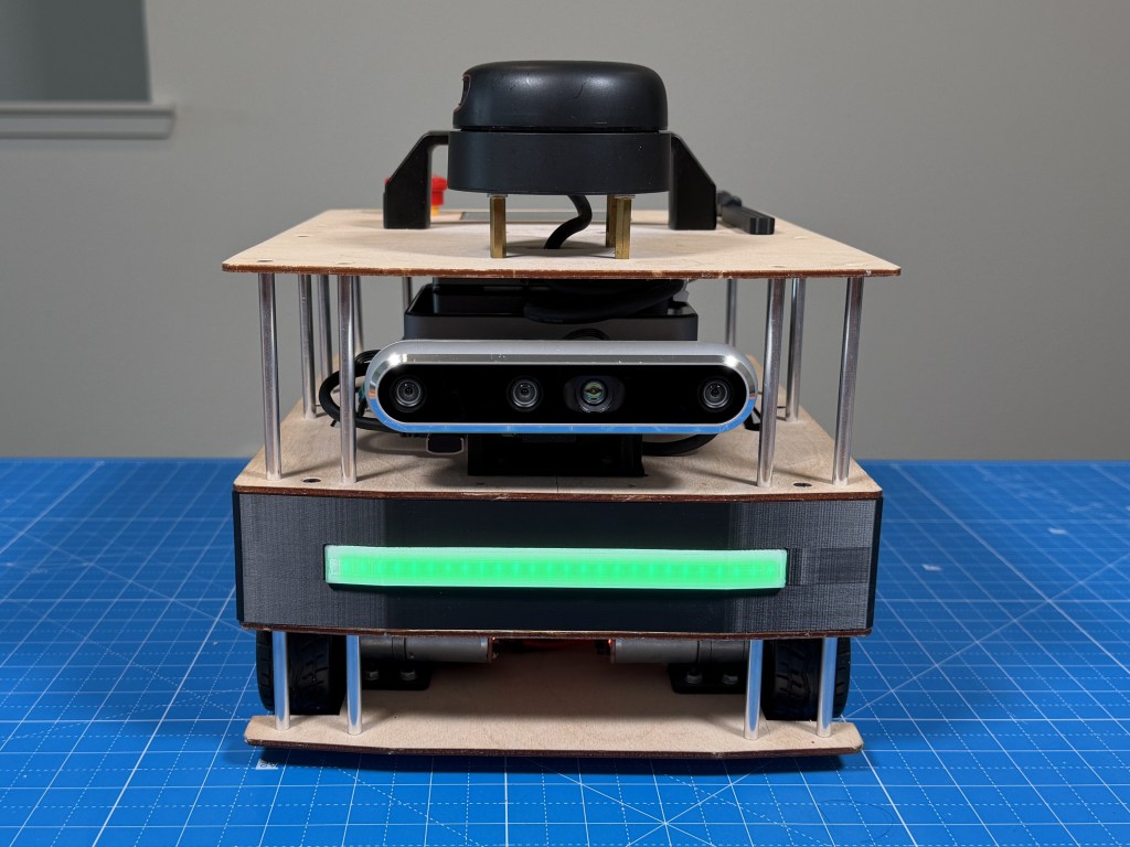
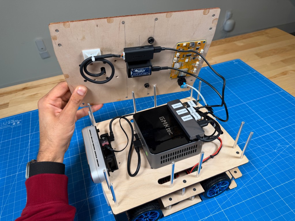
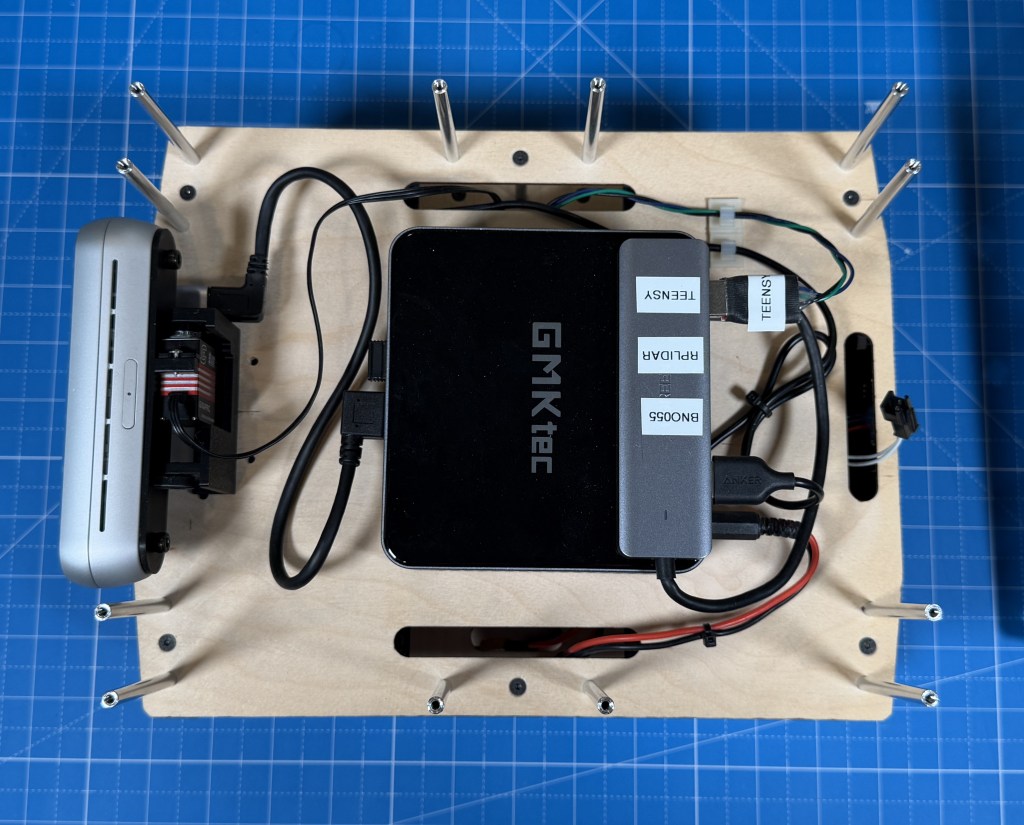
The top stack is the main sense and compute stack with the center piece being the mini pc running Ubuntu and ROS2 on it. Connected to it is a Realsense D455 RGBD camera mounted on a servo based gimbal. The computer is also connected to the RPLidar A2M8 and a ESP32 based display module. The e-stop is located on the top as well. I also have a BNO055 connected to the PC using a FTDI converter board.
For the construction, I chose simple 3mm birch plywood, interconnected with M3 standoffs. This seemed like the best option for me and allows for easy modifications and access. I have slowly added 3d printed brackets here and there to mount some external parts like the switch, led strip, oled display. I have changed the robot a fair bit since I first built it and the plywood has helped as its easy enough to drill new holes to reposition things.
Component Selection
Lets dive more into the thought process behind the components I picked for the robot including some that I removed after testing them.
Lidar
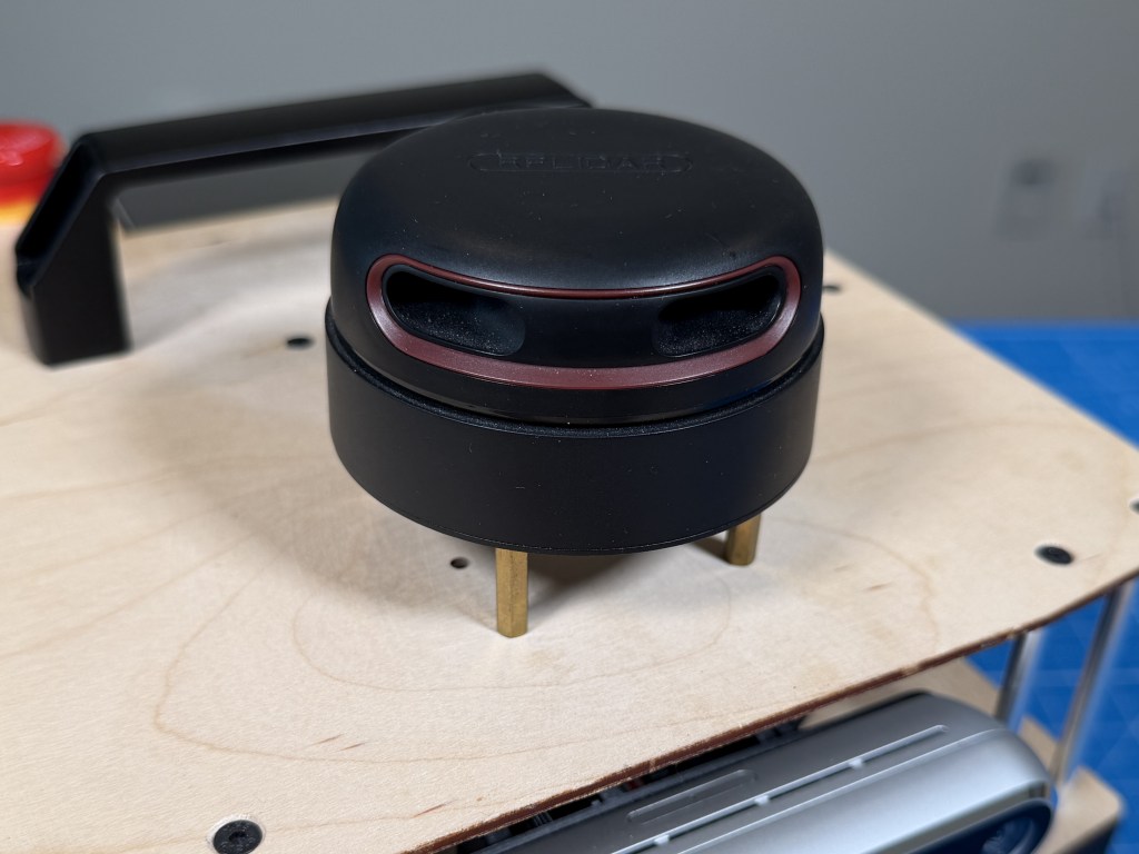
At the time I was designing it (2020), there were not many affordable (sub $500) LIDARs that also had decent performance. RPLidar A2 series seemed like the best bang for your buck. I was able to get a used A2M8 from eBay for $140 which was a pretty good deal.
I did struggle with the lidar due to a peculiar issue it had with over voltage protection being set at 5.3V and my mini PC outputting around 5.35V on the USB port. The issue was a pain to find but once I found it, solving it was easy and since then, the lidar has been fairly reliable.
Although now, better lidar technology is available at an even better cost like the RPLIDAR C1 or S2 which is ToF based and costs only $70. I also have been finding brand name lidars like Hokoku, Sick, Velodyne on eBay for a pretty good price which could end up being more reliable option.
Depth Camera
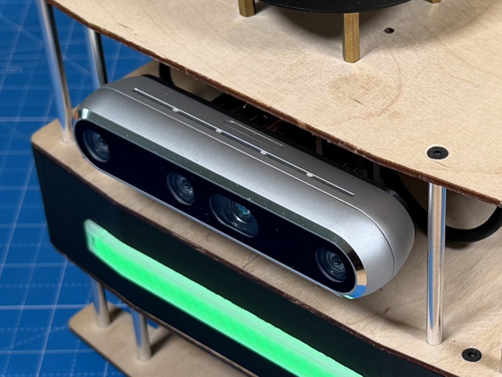
At the time, Realsense were the best quality RGBD cameras on the market with good support at a decent price. So the choice was fairly simple. I had also used them on a university robot before so was familiar of their ROS compatibility. Plus their specs compared to other options was the best bang for buck.
Over the years, seems like despite many other options being available at similar price points, the Realsense cameras are widely used and a lot more expensive now than they used to be. I have not utilized them in the robot too much yet but I do notice that the main color camera is not very high resolution and also does poorly in lower light.
Tracking Camera
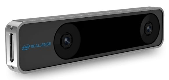
Intel Realsense T265
Initially, I added a Intel Realsense T265 tracking camera because I thought it would be good to have another source of robot pose that I can fuse with lidar and odometry based estimate for a better overall estimate. But after some testing, I couldnt get it to work well so I chose to remove it and if I do want visual SLAM, I should be able to use the RGBD camera for that, although that would add processing load to the CPU.
GPS
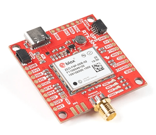
Initially I was imagining this to be operated outdoors but I never really designed the rest of it for outdoor use so having a GPS on it was a bit redundant. Its a pretty expensive RTK GPS module so I removed it to use on a robot designed for the outdoors
IMU
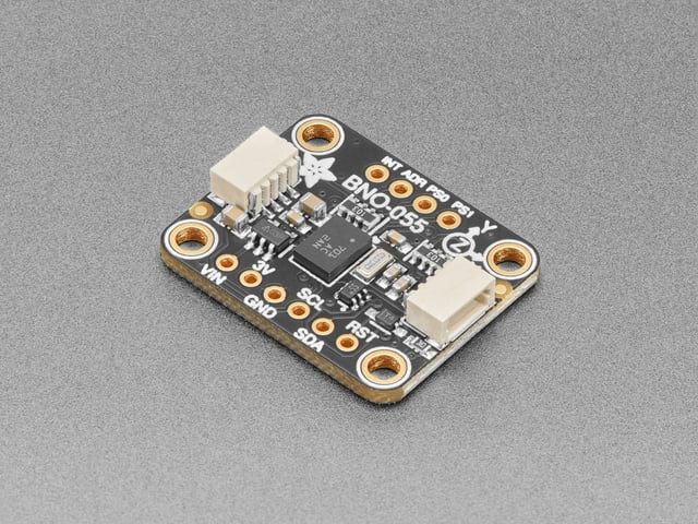
The BNO055 is a good choice since it has onboard fusion for orientation estimate. Among the options available, it seemed like a fully featured option that wont limit my experimentation with different algorithms later. I have only tried to use it to improve odometry so far with mixed results. But that is likely lack of experience and knowledge on my part.
Motors
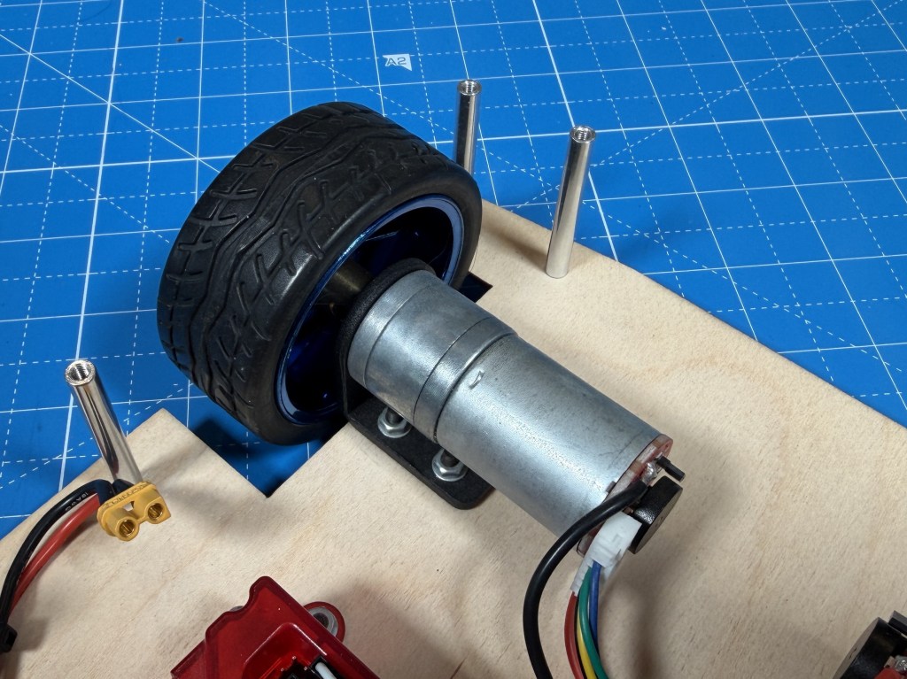
GA25-370 12V 280rpm
When I picked these motors, I went based on my intuition and experience having built robots before. And the gear ratio was picked based on a reasonable speed I wanted to hit. And it worked out well because the motors work well on the robot.
But lets do some calculations so see how well I did. The robot weighs roughly 7 lb (3.175 kg), runs on four 65 mm diameter driven wheels (radius = 0.0325 m), and needs to handle a 5° incline at up to 1 m/s with 1 m/s² acceleration.
Required torque and speed:
F_total = m×a + m×g×sin(5°) = 3.175 + 2.72 = 5.89 N
Torque per wheel = (5.89 × 0.0325) / 4 = 0.489 kg·cm
Target wheel RPM = (60 × 1) / (2π × 0.0325) = 294 RPM
Selected motor: ~280 RPM no-load, 2 kg·cm stall torque at 1.8 A.
On 5° incline (worst case):
Stall torque usage = 0.489 / 2 = 24.5% — within continuous duty range
Speed under load = 280 × (1 − 0.489/2) = 211 RPM → 0.72 m/s
Current per motor = 1.8 × (0.489/2) = 0.44 A
On flat ground:
Torque per wheel = (3.175 × 0.0325) / 4 = 0.263 kg·cm → 13.2% of stall
Speed under load = 280 × (1 − 0.263/2) = 243 RPM → 0.83 m/s
Current per motor = 0.24 A
Total system draw stays under 2 A even in the worst case, keeping things efficient and thermally safe. So the motor selection was done well and there is good amount of margin. I probably could have opted for a lower gear ratio but the robot is already pretty fast as it is so I dont think I would benefit from the extra speed.
Motor Controllers
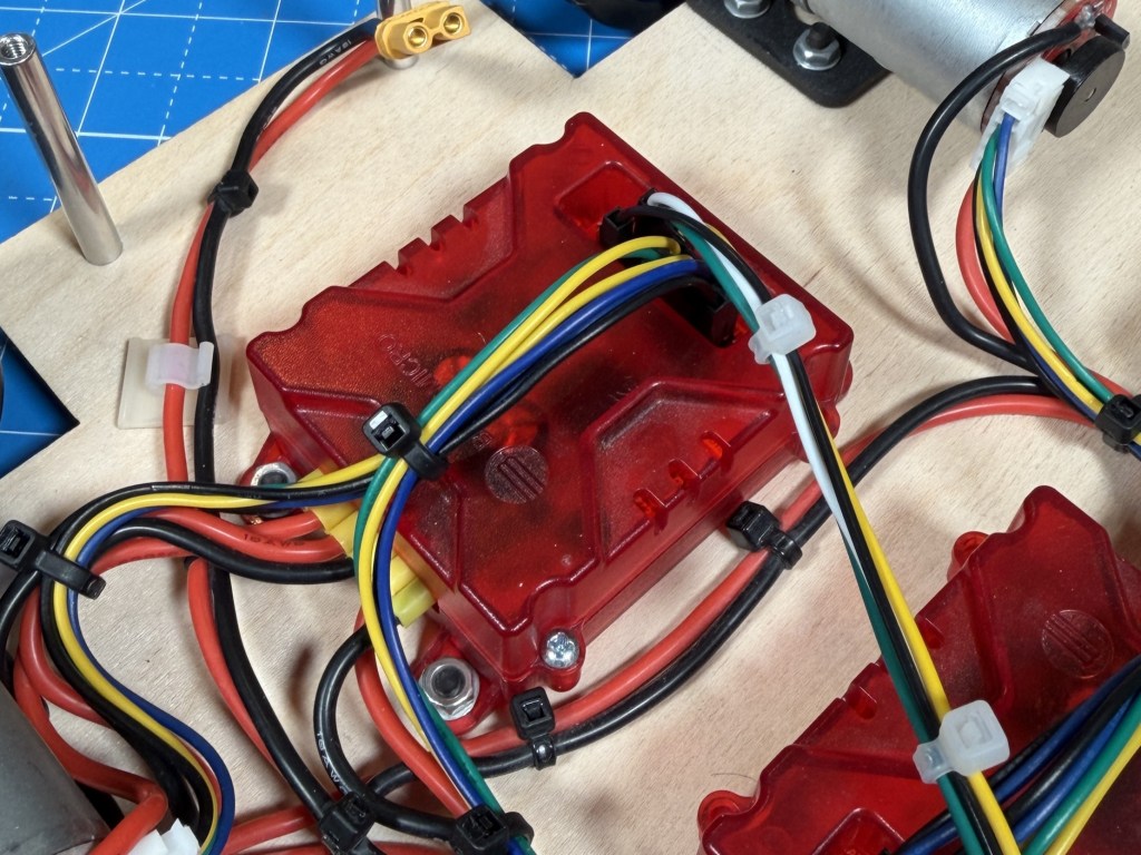
The Roboclaw seemed to be the best and easiest to use option at the time. It connects directly with encoders and has a variety of configuration options. Documentation is also pretty great so I picked them. Although I have had issues with Roboclaw changing the hardware/software and it being not compatible with older versions of the motor controller. I also have this intermittent issue where it hits the current limit at slow speeds. Maybe noise in the power measurement section, I am not sure. In hindsight, I would say they are okay, not the absolute best and completely pain free experience I thought it was going to be.
Microcontroller
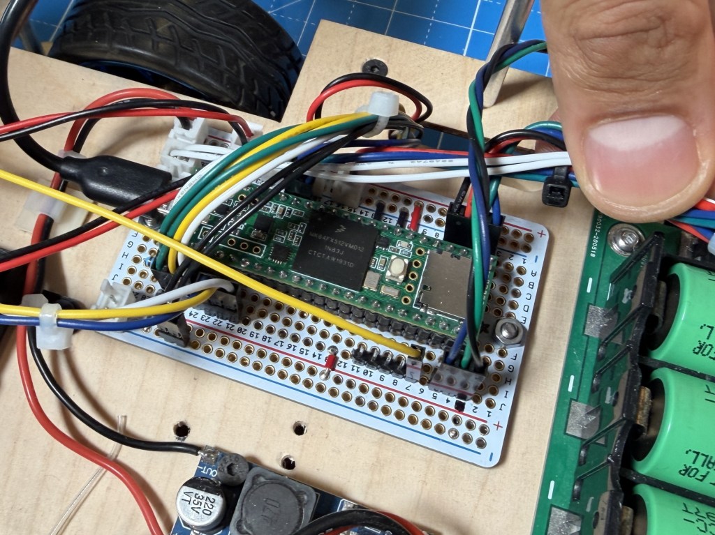
There are many Arduino compatible boards available but Teensy were and still seems to be the only good option for having loads of IO, peripherals, small footprint and Arduino compatibility. I have not come across other Arduino compatible boards that offer similar features.
Computer
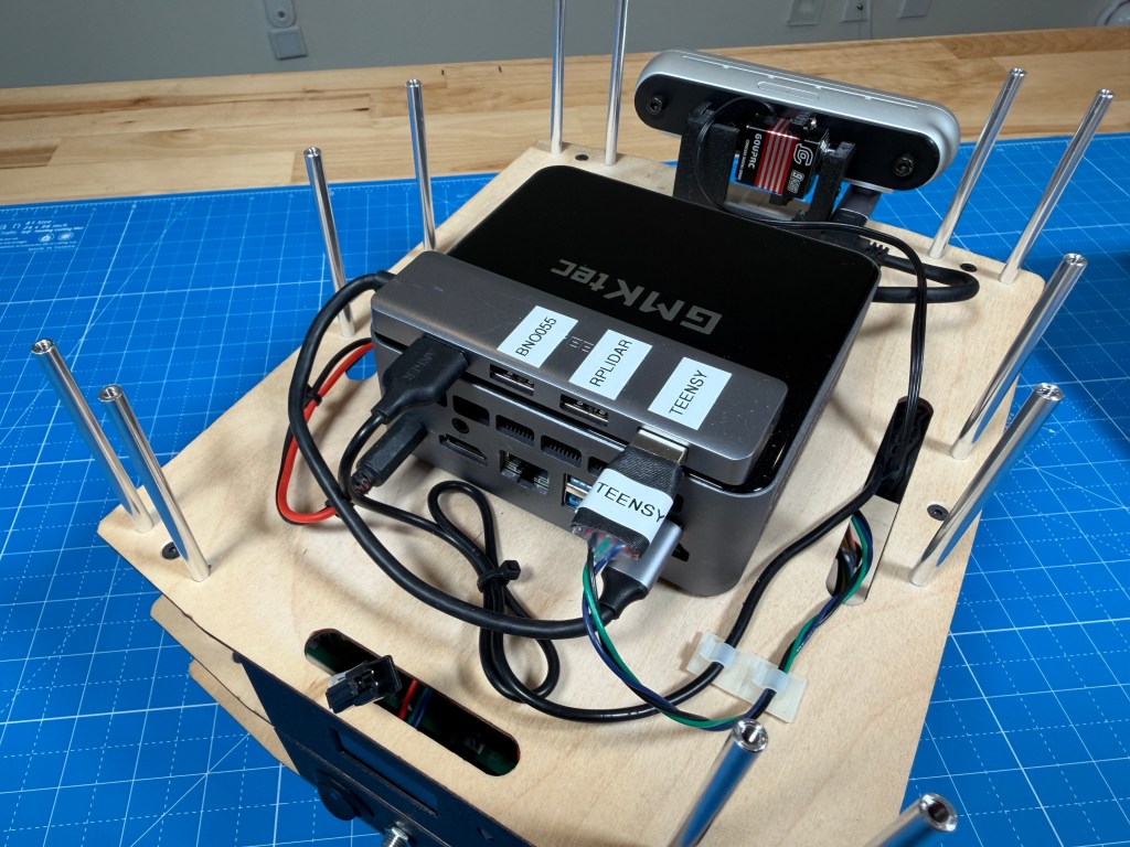
GMKtec Mini PC (Intel Core i7-1185G7 32GB 1TB)
I had worked on a university robot project where I was told that best platform to run ROS reliably, is an Intel based PC running Ubuntu. That limits the options and when looking at small form factor computers, the Intel NUC was a good option. It was sold not as a robot computer so didnt have the premium that some purpose built robot computers had. I picked up a used one from eBay for a pretty good deal.
Later, I ended up upgrading to an even newer mini PC, also running an Intel i7-1185G7 CPU with better performance and efficiency. It can still pull upwards of 60 watts under load but the development experience has been great and I have not ran into any ROS compatibility issue like on other ARM based stuff. Of course it has a mobile CPU with no real GPU or accelerator so AI inference would not work super well. Having ran some ML image detection models, it does get loaded pretty heavily with that. So will see what is possible. Being limited on compute is part of the challenge for a mobile robot.
Battery
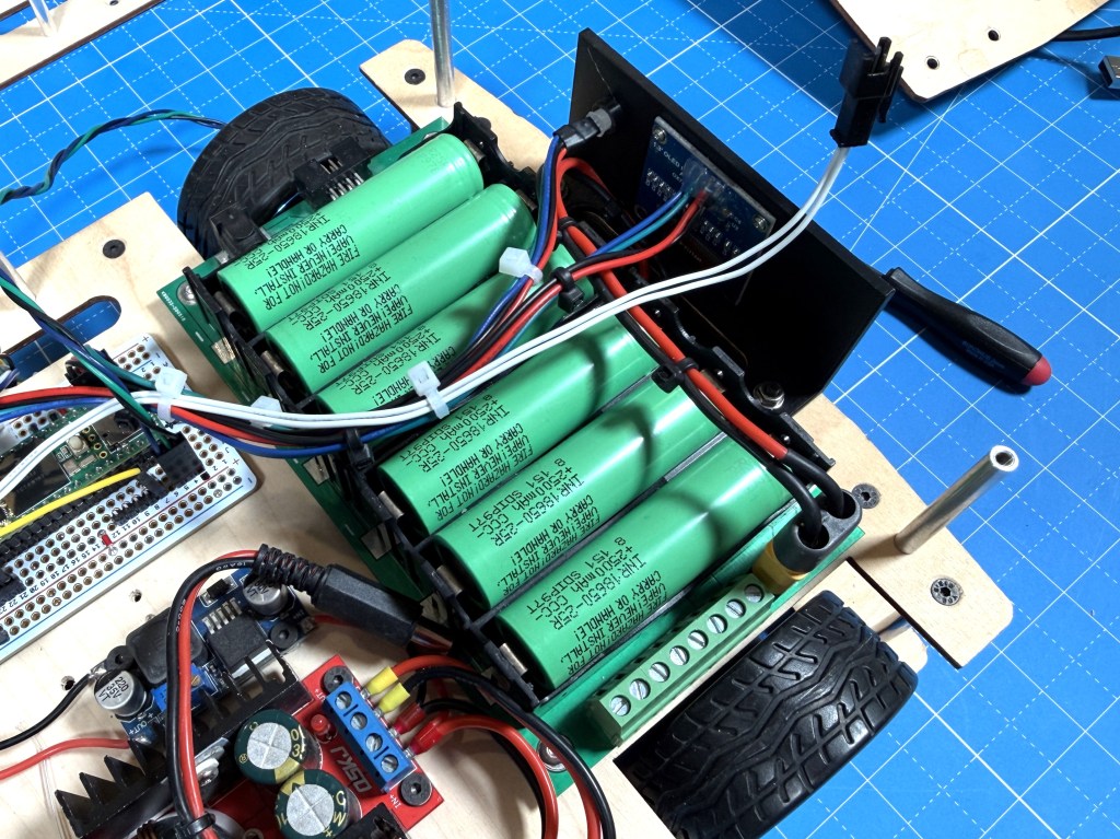
For the battery, I picked this 18650 3s2p carrier board with integrated BMS that I can load with cells of my choice. At the time I picked it, it was a good option that fit well in the space I had and provided flexibility. If I were to build it again, I would likely pick some pre-packaged packs that I can easily load in and swap out if needed. Not sure which ones but a more packaged solution would probably be safer and more reliable.
Power Sensor
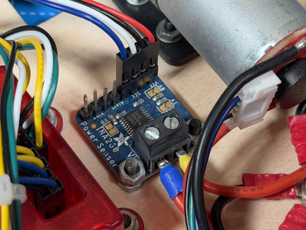
The INA260 is a simple solution with enough current capacity for my robot and a simple I2C interface for communication.
Software
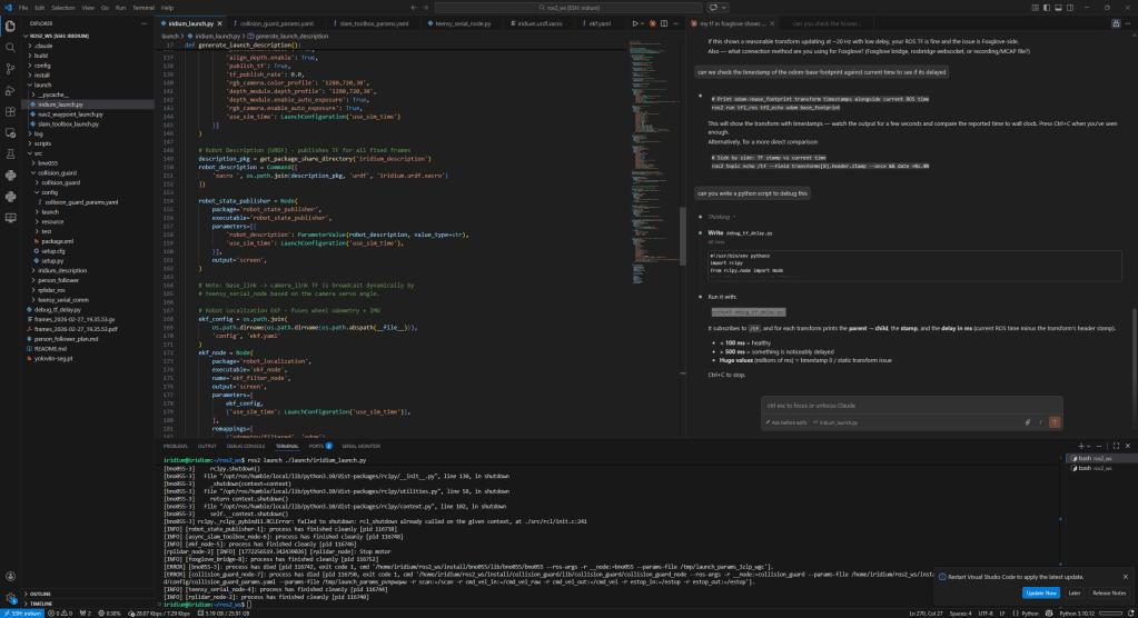

The main computer is running ROS2 and communicating with the microcontroller over serial. I do remote development using VSCode and use Foxglove for the visualization. The main things I have working so far are the interfaces to the microcontroller and all the sensor drivers. I have started playing with SLAM, navigation, person tracking etc but there is lots left to be explored. I am trying to build it one step at a time and really understanding each part before moving to the next step in the stack.
There will likely be future posts about things that I try on the robot and what I can make it do.
ROS-Teensy Interface
Github Repo: Link
The Teensy code is written in Arduino IDE for ease of development. I also picked this back when I first built the robot and just kept it instead of switching to something with better performance.
The code is running multiple loops at different rates according to task priority. The fastest loop is the control loop that is looking at motor control, e-stop and radio messages. The encoder enable forward kinematic to be done to figure out the robot position and velocity. The radio message or commanded velocity is fed into the inverse kinematics to determine the motor speeds.
The repo has more detail about the code and its architecture. I tried my best to keep it as modular as I could so that its easy to understand and debug.
Initially, I was using the ros-serial interface and it worked fairly well but when I switched to ros2, that was not supported. I didnt like the bulk of microROS so instead, I developed a custom UART communication procotol to communicate between the python ROS node and the Teensy over UART. The messages are custom designed so have minimal overhead, have CRC error checking and can be extended per the robots needs.
The interface is able to sync the time between the two to make sure odometry and other sensor messages have correct timestamps from when they were captured. The odometry communication runs at 20Hz while sensors run at 5Hz since they are not fast updating.
There are status messages that are surfaces to ROS allowing for easy debug if something is not working right. All the ROS related stuff is managed in the python node while all the ROS-Teensy communication is kept as low level and compact as possible to make it fast and lightweight.
Foxglove Visualizer
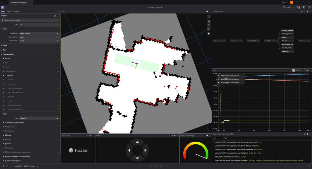
Foxglove has been pretty good to remotely visualize the robot. It does have some quirks but I was not really able to get Rviz set up remotely and hence this was the only good option. I still am figuring out the best way to develop remotely. I have not looked into remote desktop solutions, that might be something I explore. Foxglove struggles with camera feeds and higher data since its all streaming raw data over the network.
Interesting Bits
There are interesting bits of the robot I wanted to mention.
External Power
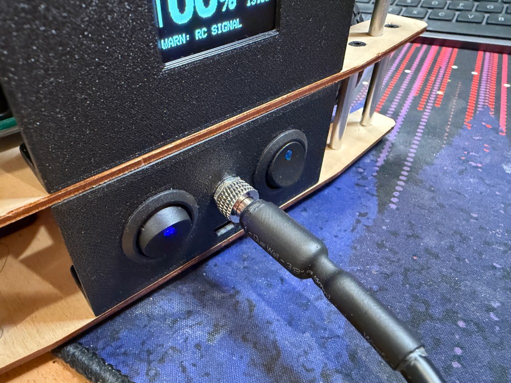
I have the option to externally supply 12V to the robot, bypassing the battery. That way, I can keep the robot powered on for days while I develop. The connector is screwed in and I built a long cable so that I can still drive it around a fair bit.
Status Monitoring
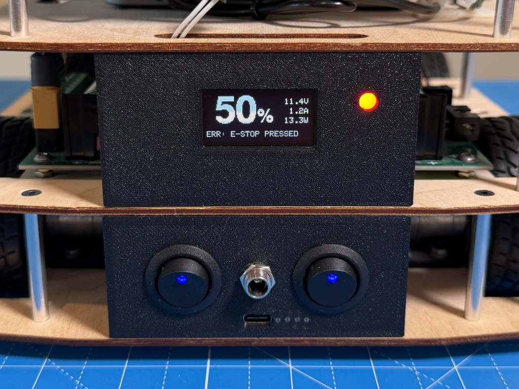
The OLED display and status LED are great for battery percentage and error messages from the microcontroller. I detect different things like no motor power, e-stop engaged, control loop timing issues, communication issues etc to flag the errors. That has made debug a lot easier and I dont have to keep wondering what is going on. I think in robotics, its really important to be able to quickly check the health of the whole robot at a glance, especially when debugging issues.
The front light strip provides a way for ROS to set a color and be able to show status of the ROS software that us running. It also is really handy and easy to tell during testing which state the robot is in.
The touch display on the top will also be programmed eventually to set and monitor things in more detail. I am thinking of having multiple modes for the robot like person tracking, exploring, mission mode etc and be able to select them from the display. But I have not developed that yet.
Camera Servo
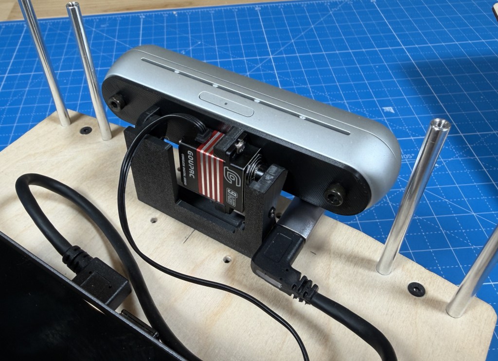
I wanted to be able to position the camera for the task, like down for obstacle avoidance and up for person tracking so the best option was to mount the camera on a servo. And its great because I can position it as I want, and the camera TF can be set accordingly in ROS so that everything is synced.
Quality of Life
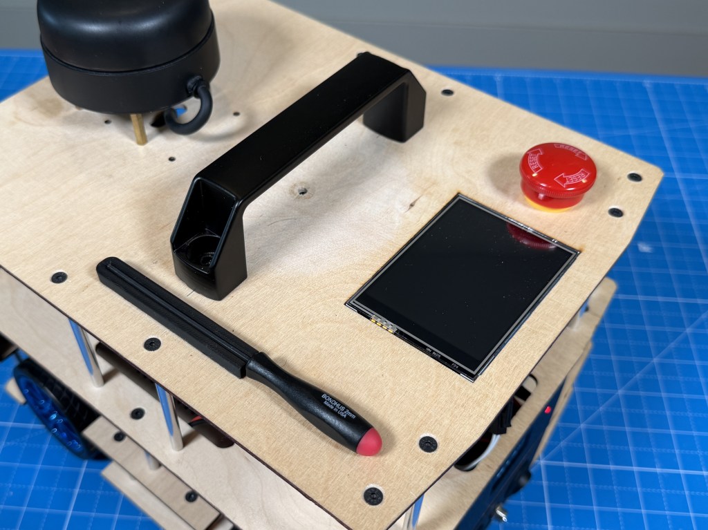
I added a handle which is super handy to move the robot around and carry it. I also added a magnetic mount for a 2mm hex driver since almost all the screws use that and I can use it to quickly remove the stacks and access anything I need.
Future Work
The hardware on the robot is pretty stable now and I am pretty happy with it. Now, there will have to be a bunch of work done on the software side to enable different types of modes on the robot. Claude has made programming a robot a bit easier so hopefully I will be able to accomplish some of the goals I want with the robot. I have already been able to do way more than I thought with the software.
Conclusion
Thanks for reading about my robot. If you are interested in a more detailed build guide or have specific questions about the robot, feel free to leave them below.

Leave a comment