RGB Cylinder Lamp
2021
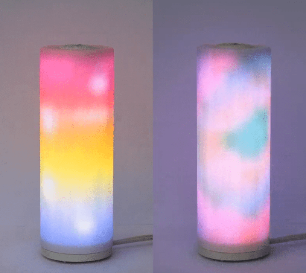
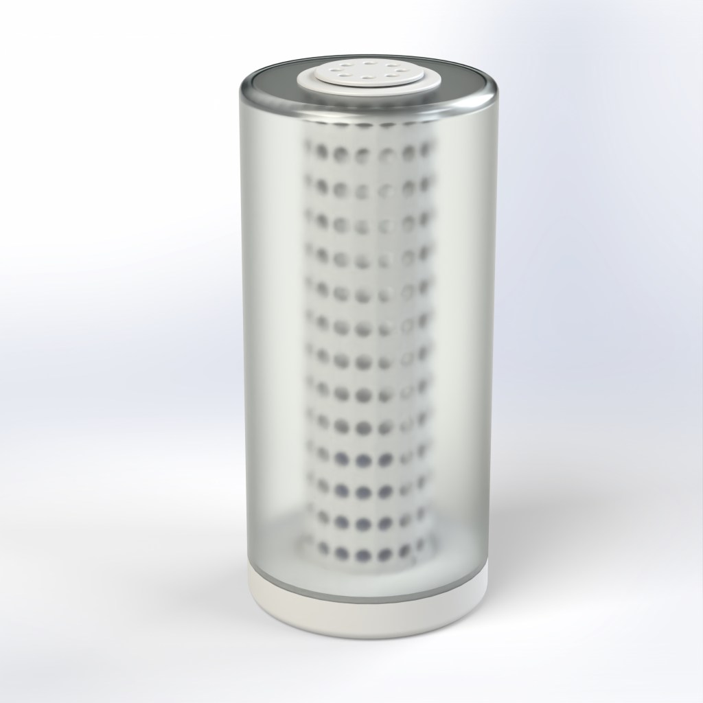
The RGB Cylinder Lamp is a custom designed smart lamp. It boasts a grid of ~200 WS2812B RGB addressable LEDs inside a frosted glass cover. The base is 3D printed and contains the Raspberry Pi Zero W that controls the LEDs. It can be controlled via the encoder wheel on the top or through a mobile app.
Continue reading to learn more about the design process and details on the various parts that make up the lamp. I am not including a build guide since this project isn’t fully completed but let me know if you would want a build guide.
Project Links
Background
The idea for the lamp came from this instructable where Gosse Adema created a beautiful RGB matrix lamp. His write up is absolutely amazing and it inspired me to build something like that myself. I liked the general idea but I wanted to put my own spin on the design, improving it in various areas.
There were two main issues with his design that I saw. One was that I wasn’t happy with the cost of the glass cover he recommended. I wanted to find something cheaper. And second was that I didn’t like the very DIY nature of the base and interior design. I wanted to improve it so that it can be easily put together and taken apart. I also wanted to have a cleaner hardware design by using a custom PCB.
Design
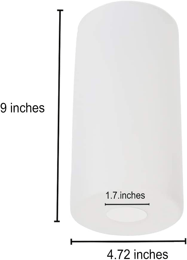
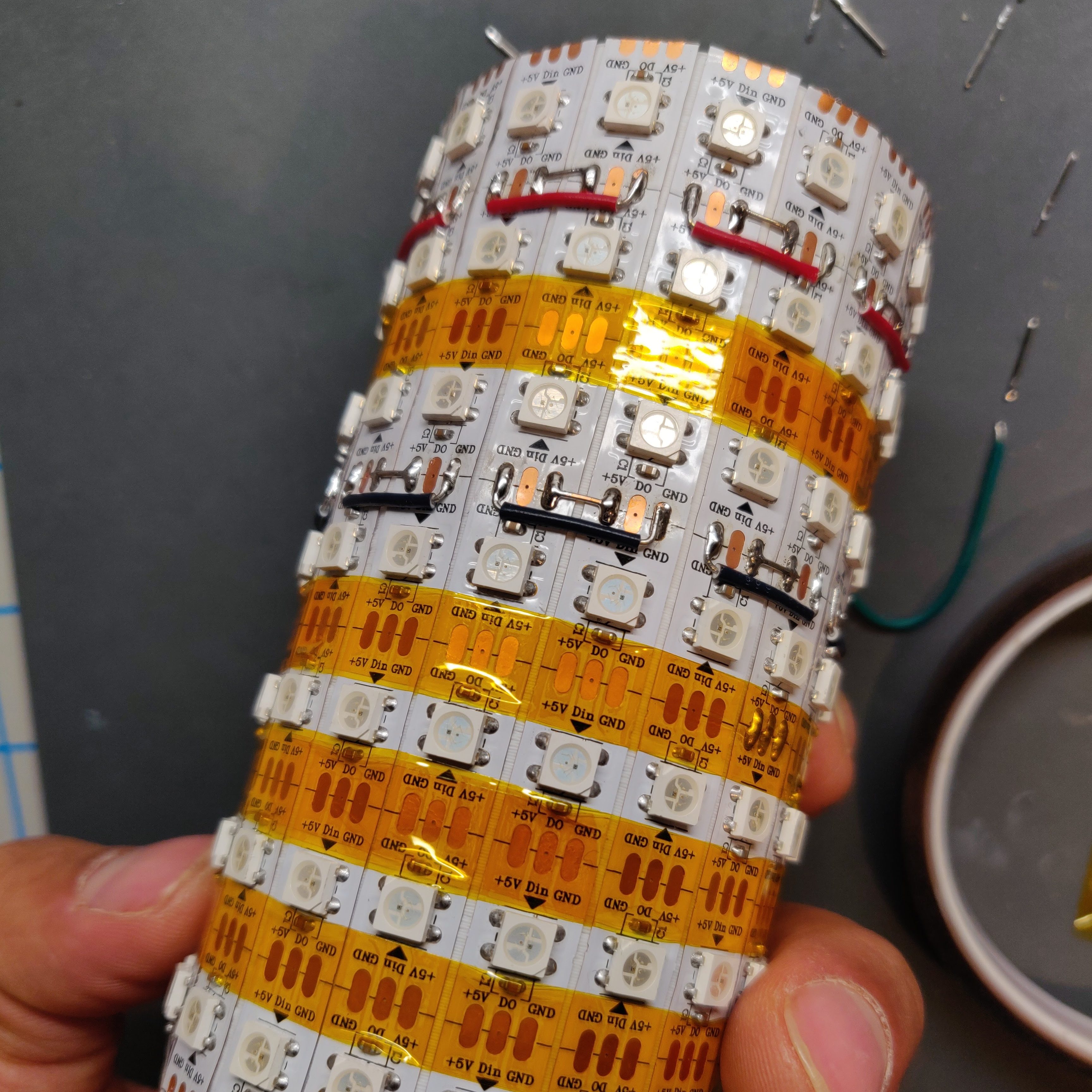
The center piece of the design is the frosted glass cover. I found this lamp shade that was roughly the size that I was looking for and cost half as much as the one in the instructable. I went ahead to design the lamp around this cover. The design would also be dependent on the type of LED strip that I used. The one used in the original design wasn’t easily available so I selected this 60 LED/m WS2812B RGB strip.

I went through a few iterations of the design. Initially, I tried to print the models from the original design, modified to fit my LED strip. But I soon learned about its limitations including the difficulty to assemble, poor thermal management and the need for tight tolerances. The LED strip that I was using didn’t have very consistent LED spacing so they were very hard to assemble.
My second design had a light column on which the LED strips were mounted externally. This was in contrast to the original design where the LED strip mounted from the inside.

I also wanted to have a user input mechanism that integrated well with the design. What I came up with was a rotary encode and tactile button combo on top of the lamp. Power was supplied using a USB-C port. I also had a cooling fan on the base that would provide air circulation through the center column.
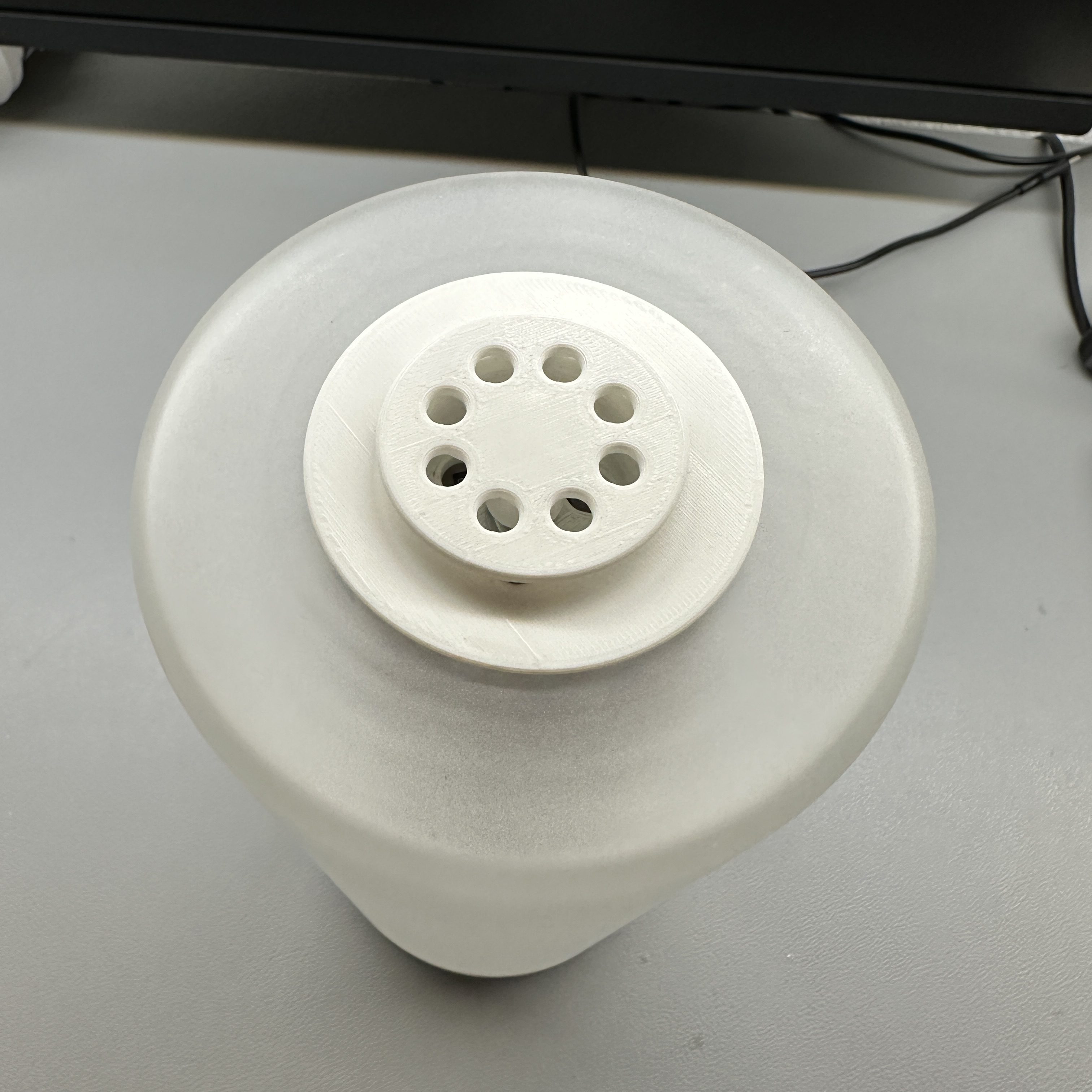
The second design looked great but the base wasn’t well designed and it had to be glued in place. The final design had a lot of internal changes with minimal external change. I was able to design the plastic parts in a way that they were held together with screws and could be easily taken apart.
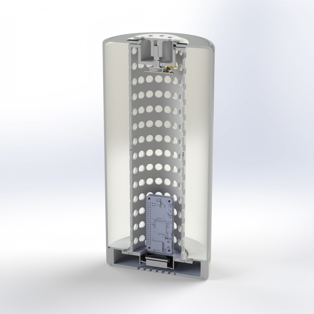
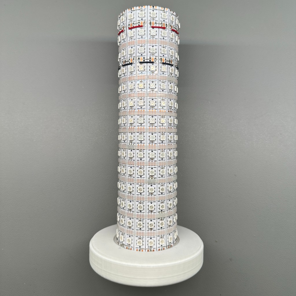
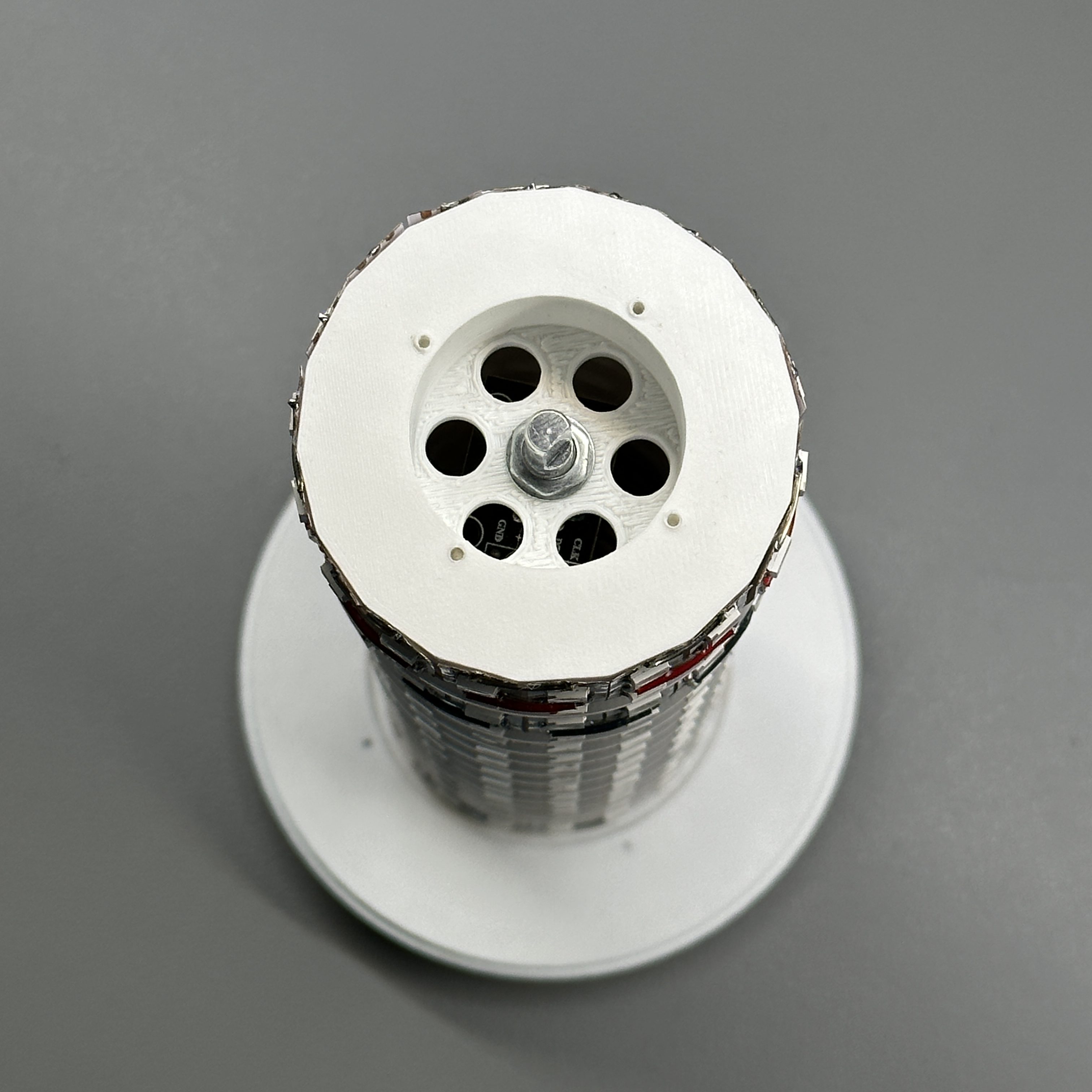
In the final design, I used white zip ties to hold the LED strips in place so that they wont show through the glass as the kapton tape did. The LED column was printed in two parts and then glued together due to printer limitations. The column had a flange on the bottom that held onto the base and it had screw holed on the top so that it can be screwed into to secure the top, inner and bottom pieces together with the glass lamp cover.
PCB
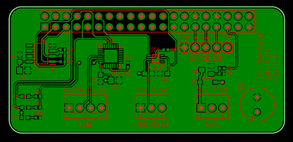
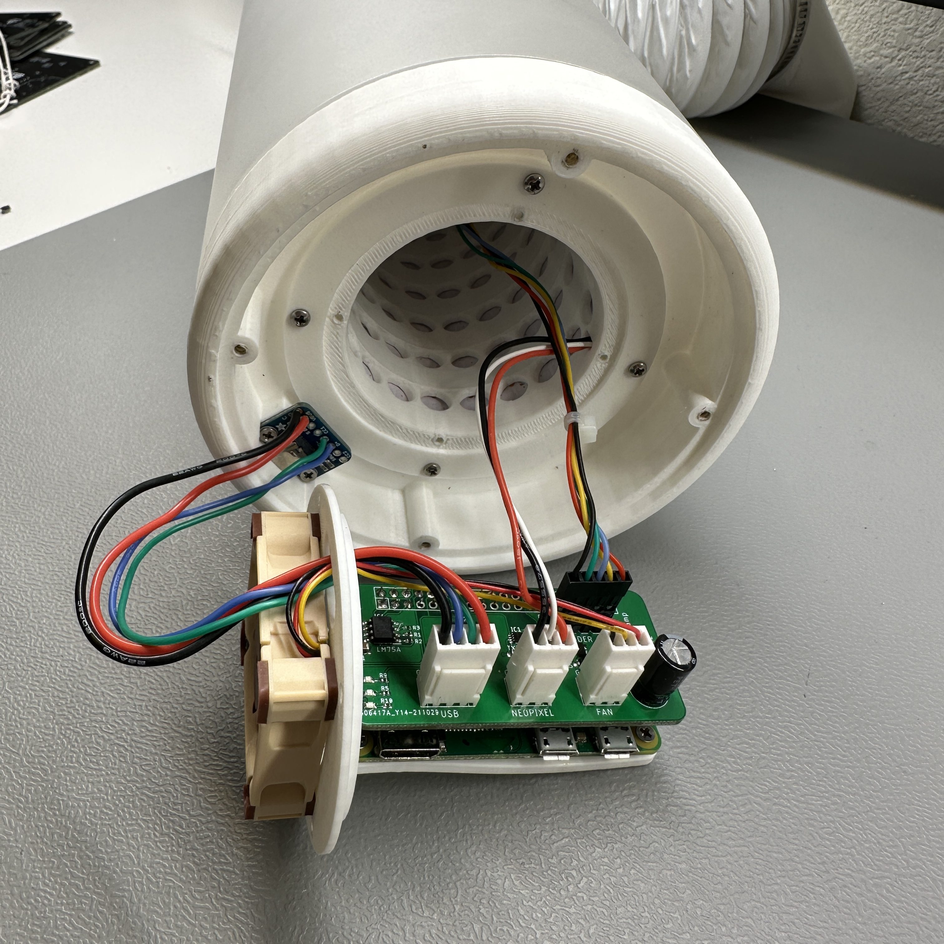
The PCB is designed as a hat for the Raspberry Pi Zero W. Its a simple design with some connectors and components required to interface with the external components. It has the following sections.
- CC22102 USB serial IC to communicate with the Pi over USB
- LM75A temperature sensing IC and MOSFET switch to control the cooling fan
- TXB0102 level shifter IC for the LED strip logic
- Connectors for the USB, LED strip, fan and encoder
The PCB is a fairly straightforward design as it was one of my first custom SMD PCB design. I designed it in Eagle and learned a lot about how to design footprints such that they are easy to solder. I assembled the board by hand using the flux -> tin -> place -> reflow method. This method doesn’t require a stencil and works fairly well although the picture below is my first attempt at it so its not the best result.
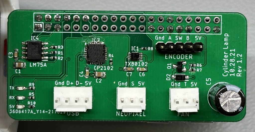
My main learning from this PCB design was understanding WS2812B addressable LED data timing requirements. I originally had a simple MOSFET based level shifter implementation to convert the 3.3v logic level to 5v. But when it didn’t work, I dug deeper and learned that the frequency of the data line is too high for the MOSFETs. That is when I switched over to the dedicated TXB0102 level shifter IC.
Cooling
The LED strips generate quiet a bit of heat that gets trapped inside the light tower. Since the plastics are 3D printed PLA, cooling is important to keep them from melting. I could have used a more thermally resistant material but when I was designing it, I thought cooling would be a better solution.
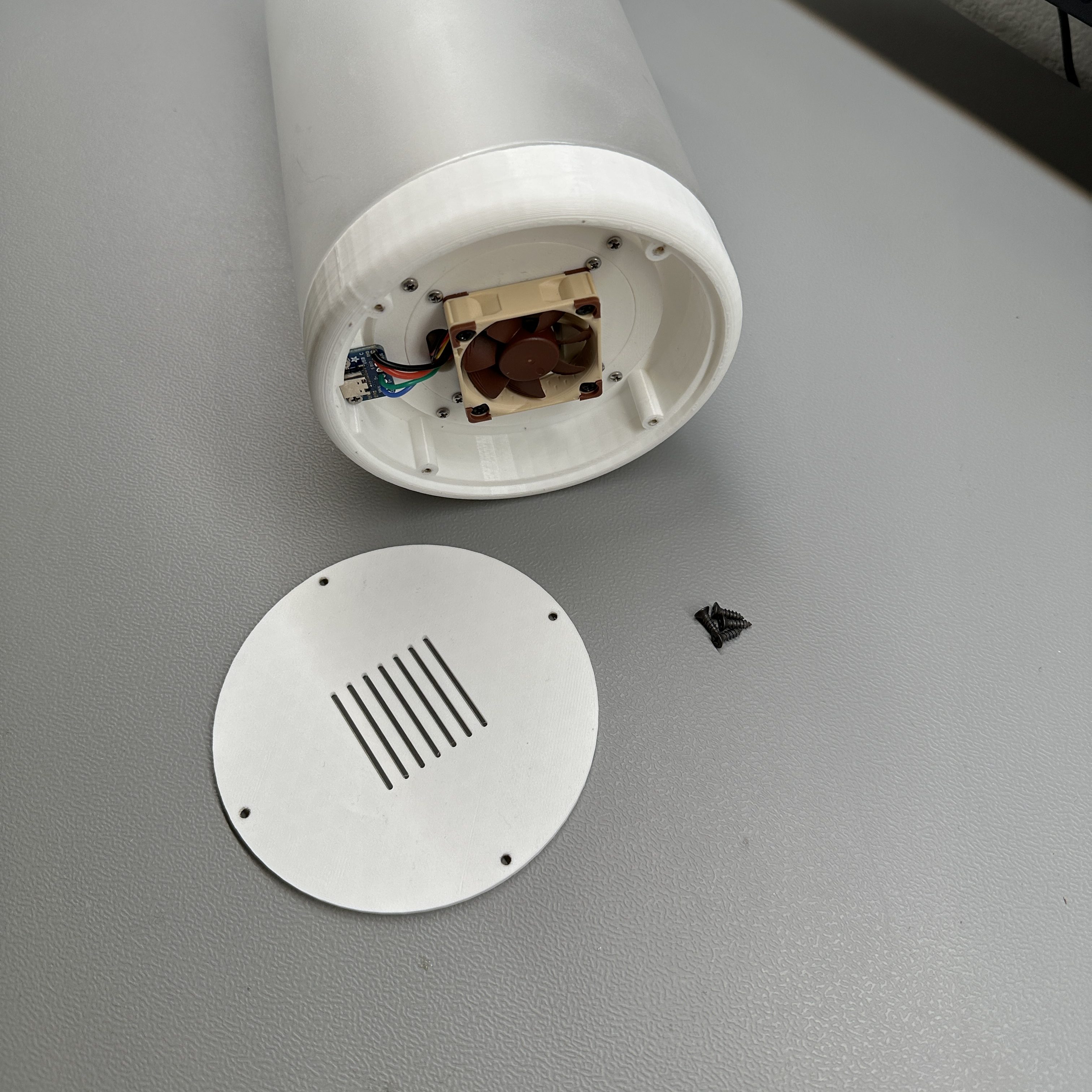
The light tower along with the pieces on the top and bottom are designed to allow for air to flow in from the bottom and out from the top. I have put a Noctua 40x40x10mm fan to assist with the air flow. The fan is controlled by the Raspberry Pi which has a temperature sensor so it turns on only when needed.
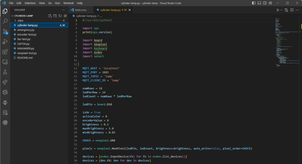
Software
The software is written in Python for the Raspberry Pi. I use libraries provided by Adafruit to control the LED strip. I only have a simple RGB sequence script written that uses the encoder to change the brightness and turn the light on and off. I use supervisord to automatically launch the python script at boot.
I need to do more work on the software side to make the lamp more useful. I want to add more color modes, display weather and be able to control it remotely.
Conclusion
I hope you enjoyed reading about the RGB Cylinder Lamp. I know the name is a bit boring but I am open to ideas. Let me know if you have any questions or if you would like me to add a detailed build guide. Thank you.
One response to “RGB Cylinder Lamp”
-
Love it
Great project! The design is impressive and the use of a custom PCB and smart features make it even more interesting. Looking forward to seeing more updates on the software side too.
Eamon O’Keeffe
Great DIY Ideas

Leave a reply to DIY Home Improvement Cancel reply